Context:
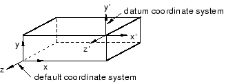
The figure below shows an example of creating a rectangular datum coordinate
system at an offset from the default coordinate system.
When
Abaqus/CAE
prompts you to select a point, you can select the origin of a datum coordinate
system. When
Abaqus/CAE
prompts you to select an edge, you can select one of the axes of a datum
coordinate system.
From the main menu bar, select
.
The Create Datum dialog box appears. The dialog
box outlines the types of datum geometry you can create.
Abaqus/CAE displays prompts in the prompt area to guide you through the procedure.
From the list of types at the top of the dialog box, choose
CSYS.
The Method list indicates the methods you can
use to create a datum coordinate system.
From the Method list, select Offset
from CSYS.
Abaqus/CAE
displays the Create Datum CSYS dialog box.
From the dialog box, enter the name of the datum coordinate system.
To help keep track of your datum coordinate systems,
Abaqus/CAE
displays its name in the
Model Tree.
In addition, you can use the
Model Tree
to rename the datum coordinate system.
From the dialog box, select one of the following datum coordinate
systems:
-
Rectangular: The
X-, Y-, and
Z-axes are aligned with the 1-, 2-, and 3-global
axes, respectively.
-
Cylindrical: The
R-, -,
and Z-axes are aligned with the 1-, 2-, and 3-global
axes, respectively.
-
Spherical: The
R-, -,
and -axes
are aligned with the 1-, 2-, and 3-global axes, respectively.
From the Create Datum CSYS dialog box, click
Continue.
If desired, select Make Independent from the
prompt area to create the datum as an independent feature.
From the current viewport, select a datum coordinate system.
From the buttons in the prompt area, select one of the following:
- Enter
Value
-
In the text field in the prompt area, enter the
X-, Y-, and
Z-coordinates of the offset from the selected
default coordinate system.
- Select Point
-
From the part or assembly in the current viewport, select a point to
define the offset from the selected default coordinate system.
The datum coordinate system appears. You cannot move or rotate a
datum coordinate system.
 tool, located in the module toolbox. For a diagram of the
datum tools in the toolbox, see
Using the Datum toolset.
tool, located in the module toolbox. For a diagram of the
datum tools in the toolbox, see
Using the Datum toolset.