Controlling shell thickness display

Displaying shell thickness enables you to examine the thickness of shell geometry relative to the rest of the model. You can apply a scale factor to reduce or increase the display of shell thickness for your session.

Related Topics
Defining sections
Customizing geometry and mesh display
Controlling shell thickness display for postprocessing

Context:

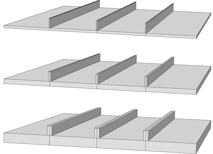
If you use shell elements to model relatively thin components in your analysis, you can use the ViewPart Display Options and the ViewAssembly Display Options menu options to view the actual thickness of these shell elements in your model. Figure 1 shows the effect of scale factor changes displayed on the stiffened plate model described in Will link to gsa-mat-exablastload.

Figure 1. From top to bottom: shell thickness scale factor settings of 1 (default), 2, and 4.

Abaqus/CAE renders shell thickness for three-dimensional shell elements only; thickness is not displayed for axisymmetric shell elements, such as SAX1 elements. When shell thickness is displayed, Abaqus/CAE also renders the edges of shell geometry unless a view cut is displayed in the viewport. Abaqus/CAE renders shell thickness according to the current settings for color coding and translucency. When these settings change, the color and translucency of the shell thickness change as well.

If a discrete field has been used to define shell thicknesses or the shell offset, the Render shell thickness option has no effect. The shells are always displayed with zero thickness and no offset.

  1. Locate the Render shell thickness option.

    From the main menu bar, select ViewPart Display Options or ViewAssembly Display Options. In the dialog box that appears, click the General tab.

  2. From the bottom of the dialog box, toggle on Render shell thickness to display shell thicknesses for the shell sections in your model.

  3. If desired, apply a Scale factor to the shell thicknesses to increase or decrease their thickness. The default value is 1, which produces a realistic rendering of the shell thickness settings.

  4. Click OK to implement your changes and to close the dialog box.

    Abaqus/CAE displays the shell sections in the selected part or assembly with the appropriate thickness. Your changes are saved for the duration of the session.