Creating virtual topology based on geometric parameters | ||
| ||
Edge length
Face size
Face aspect ratio
Face corner angle
Thickness of faces representing small stair features
Corner angle for combining adjacent edges or faces
Angle and radius controls for combining blends (chamfered or rounded corners) with surrounding faces
Redundant entities
Abaqus/CAE attempts to simplify the model by merging neighboring edges and faces when the selected parameters are exceeded.
The redundant entities parameter can only be toggled on or off—there are no other settings for this parameter. Redundant entities do not add to the geometry of the model. Redundant entities include:
Edges that are interior to an existing face
Edges that separate an otherwise continuous planar or curved face
Vertices that are interior to a face
Vertices that separate two straight edges or smooth curves without connecting a new edge
For example, Figure 1 contains four redundant edges and one redundant vertex. Virtual topology will merge the edges with the surrounding faces and merge the vertex with the surrounding edges, leaving only the underlying box.
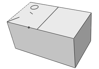
Keep in mind that redundant entities may define areas used by other tools within Abaqus/CAE. For example, the circular edge in Figure 1 may define a face for the application of a pressure load. The controls in the Create Virtual Topology dialog box are based entirely on geometric parameters; you should carefully review the changes made using virtual topology to make certain that none of the changed entities are required for other parts of the Abaqus/CAE model definition.
By default, all the virtual topology parameters in the dialog box are active, as shown in Figure 2. The default values for the edge length, face size, stair feature, and blend radius are calculated based on the size of the selected part or part instance; the other criteria are dimensionless and suitable default values are provided. You can toggle off the controls for entities that you want to be ignored by virtual topology. For example, if you have small faces that are a critical component of the model, toggle off Faces smaller than.
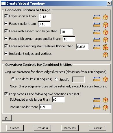
To help you review potential changes, each parameter in the dialog box contains tools that you can use to measure and highlight entities in the viewport that satisfy the corresponding geometric criteria. Items that are highlighted may not be changed if they conflict with other criteria or model requirements. To use the tools, click on the icons located to the right of each parameter in the Create Virtual Topology dialog box. The measure entities  tools allow you to measure entities in the viewport. Abaqus/CAE displays the measured values in the message area; you can use the measurements to revise the parameter limits for your model. The highlight tools, such as Highlight Short Edges
  , indicate entities that satisfy the current parameter settings. For the Candidate Entities to Merge area of the Create Virtual Topology dialog box, the highlight tools indicate entities that may be merged with the surrounding geometry.
The highlight tools do not account for the combination of parameters or any other factors in the model that may prevent the highlighted features from being merged with surrounding geometry. For example, small stair features must satisfy two parameters for replacement using automatic virtual topology:
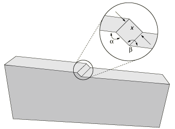
The stair height or thickness must be less than the specified value.
The opposing angles that separate the stair face from the surrounding faces must deviate from 180° by an angle larger than the specified angular tolerance for sharp edges/vertices (explained below with the curvature controls).
Figure 3 shows the angles and the face dimension that make up a stair feature. If you use the highlight tool to view potential faces, Abaqus/CAE does not consider the angle measurements when selecting the faces to highlight.
The Curvature Controls for Combined Entities area of the Create Virtual Topology dialog box is used for combining corner angle and blend entities. The curvature control parameters and highlight tools indicate edges, vertices, or blends that will be retained—not replaced by virtual topology—using the current settings. The following examples explain how the curvature control parameters for corner angles and blends are interpreted by Abaqus/CAE.
- Angular tolerance for sharp edges/vertices (deviation from 180 degrees)
Corner angles are the angles between any two adjacent faces or edges that create an edge or vertex, respectively, in the model. If a corner angle is close enough to 180° to be considered flat, Abaqus/CAE considers using virtual topology to ignore the associated edge or vertex. The default parameter setting considers angles flat if they deviate from 180° by less than 30°. Figure 4 shows how merging faces effects the resulting mesh. The two upper images use a shallow angle so the resulting mesh is a close approximation of the geometry. Increasing the angle between the merged faces as shown in the lower images yields a progressively worse approximation. The corner angle parameter also applies to face corner angles between the edges of two-dimensional parts and to the angles that create small stair features.
Tip: To keep all corner angles, specify a deviation of 0°. Figure 4. The correspondence between the mesh and the geometry decreases as the corner angles replaced by virtual topology (the peak and valley) deviate further from 180°.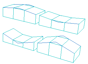
- Keep blends with a large subtended angle and a small radius
Blends—rounded or filleted corners—must satisfy two parameters to avoid consideration for virtual topology. This is due to the fact that either the subtended angle or the blend radius alone can create a feature that can be approximated well by the mesh, but combining a large angle with a small radius leads to a poor approximation. Figure 5 illustrates how two different blend angles are approximated by the mesh if they are merged with the surrounding geometry. The blend radius is the same for both parts, but the larger subtended angle in the upper image results in a bumpy mesh at the corner.
Figure 5. A large blend angle (upper image) may yield a bumpy mesh when it is replaced by virtual topology.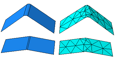
In Figure 6 the subtended angle is the same for both parts, but the small blend radius in the upper image results in a poor quality mesh.
Figure 6. A small blend radius (upper image) may yield a poor quality mesh when it is replaced by virtual topology.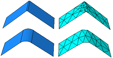
For detailed instructions on how to use the Create Virtual Topology dialog box, see Creating virtual topology automatically.