Defining the stress line | ||
| ||
A node label is a persistent means of referring to a given node in a part instance; that is, node labels do not change as your model deforms. Therefore, if you specify the endpoints of the section using node labels or a saved node list path, these points will be equally applicable to the undeformed or the deformed model shape. However, points in space remain fixed and are independent of your model. For example, coordinates that coincide with a nodal location on the undeformed shape may not coincide with any location on the deformed shape. If you specify the endpoints of the section using coordinates in space, a point list path, or a radial path, be sure to specify the coordinates with respect to the correct shape. Edge list paths cannot be used to define a stress line.
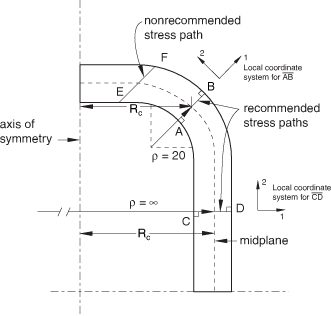
For the best results for an axisymmetric model, the endpoints chosen should be normal to the interior and exterior surfaces of your model and to the midplane (see Figure 1).

The section can extend from surface to surface, or it can be entirely in the interior of the model. The section can also pass through more than one part instance. The following guidelines should also be considered when selecting the endpoints for the section:
Avoid paths that traverse spatial discontinuities.
Avoid paths along a line separating discontinuities.
Use display groups to isolate individual regions prior to specifying the section.
If the section extends across spatial discontinuities, such as a hole within a part instance or a space between part instances, an error message will be given.
After you choose the endpoints of the section, you can specify the number of segments into which the line should be divided or you can accept the default number. Abaqus/CAE defines the stress line by interpolating between the two endpoints to obtain the specified number of equal intervals along a straight line.