Modifying or copying objects by selecting edges | ||||
|
| |||
- Translate
You can translate selected edges by specifying the start and end coordinates of a translation vector. The translation vector can start from any point; however, you may find it more meaningful to start the vector from the vertex at one end of a selected edge and end it at the vertex's new location. Figure 1 shows the selected edges, the translation vector, and the result of the translation. To achieve the results shown, Fixed constraints were added to prevent the two vertices of the upper rectangle from moving.
Figure 1. Translating selected edges.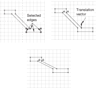
- Rotate
You can rotate selected edges by specifying the coordinates of the center of rotation and entering the angle of rotation; a positive angle indicates a counterclockwise rotation. Figure 2 shows the selected edges, the selected center of rotation, and the result of a 90° rotation. The selected edges are not connected or otherwise constrained to other edges in the sketch, so the constraint solution method has no effect on the rotation.
Figure 2. Rotating selected edges.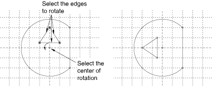
- Mirror
You can mirror selected edges by selecting a straight line in the sketch as the mirror line. Figure 3 shows the selected edges, the mirror line, and the resulting copy including a mirror constraint for each of the four selected edges. The mirror line may be any straight object line or construction line in the sketch.
Figure 3. Mirroring selected edges.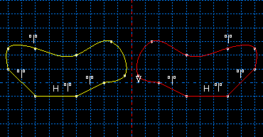
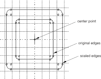
- Scale
You can scale selected edges by specifying a center point and a scale factor. A scale factor less than 1.0 decreases the spacing between the edges, and a scale factor greater than 1.0 increases the spacing between the edges. Figure 4 shows the selected edges, the selected center point, and the result for a scale factor of 1.5.
Figure 4. Scaling selected edges.