How Abaqus/CAE orients your sketch | |||||||||
|
| ||||||||
- Two-dimensional or axisymmetric modeling space
When you add a planar feature to a two-dimensional or axisymmetric part or assembly, Abaqus/CAE starts the Sketcher and aligns the X- and Y-axes of the part with the axes of the Sketcher grid, regardless of the type of feature you are creating. (Abaqus/CAE derives the X- and Y-axes of the part from the axes of the sketch that defined the base feature.)
- Three-dimensional modeling space
When you add a feature to a three-dimensional part or assembly, you must use the following technique to control the orientation of the view relative to the Sketcher grid:
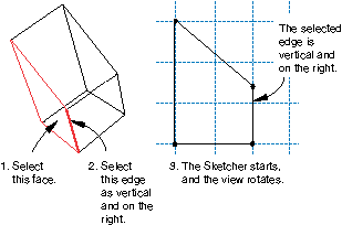
Select the plane on which to sketch by selecting appropriate geometry; for example, a face of a part or a datum plane.
Select an edge. By default, the selected edge will appear vertical and on the right side of the Sketcher grid. Alternatively, you can choose a different orientation for the edge in the Sketcher grid before you select the edge; for example, horizontal and on the top of the Sketcher grid. You can select any edge from the part or assembly that is not perpendicular to the selected plane. You can select a datum axis, or you can select one of the axes of a datum coordinate system; but you cannot select the edge of a datum plane. You can select a curved edge, but the resulting orientation of the part or assembly is system dependent.
Abaqus/CAE highlights the selected edge, enters the Sketcher, and rotates the part until the selected edge aligns with the grid in the desired orientation. The orientation of the view on the Sketcher grid also depends on the type of feature you are creating:
When you are sketching a cut feature in the Part module, Abaqus/CAE orients the view so that the resulting feature will cut away from you and into the screen.
When you are sketching a feature other than a cut (for example, an extruded solid), Abaqus/CAE orients the view so that the resulting feature will protrude out of the screen toward you.
When you are adding a swept feature, you must sketch a sweep path and sweep profile. For details of the resulting view orientation, see Adding a swept solid feature; Adding a swept shell feature; and Creating a swept cut.
When you are partitioning faces using the sketch method in the Partition toolset, Abaqus/CAE orients the view based upon the modeling space of the part or assembly and the type of faces you selected to partition. For more information, see Using the sketch method to partition faces.
If you are unsure of the part's or assembly's orientation relative to the sketch plane, use the view manipulation tools to examine the sketch plane and the object on which you are sketching. Use the reset view tool  to return to the original view.
Figure 1 illustrates how Abaqus/CAE determines the sketch plane orientation relative to a three-dimensional part after you select a face, an edge, and the orientation of the edge on the Sketcher grid.