Using the Datum toolset in the Part module | |||||
|
| ||||
Datum points are projected onto the Sketch plane in the Sketcher, and the projected point can be selected. However, you cannot refer to datum axes or planes in the Sketcher. Examples of how you might use datum planes and axes in the Part module are given below.
- Datum plane
You can sketch directly on datum planes, and any features you sketch on a datum plane will be projected onto the part. Projecting a sketch from a datum plane is useful if the part does not already contain a convenient sketch plane.
For example, suppose you want to cut a hole straight through the three-dimensional triangular part shown in Figure 1, parallel to the X-axis.
Figure 1. The desired cut feature.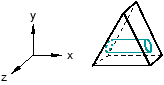
The part does not already have a face that is suitable for sketching the profile of the hole; sketching the profile directly on a face results in a hole normal to the face, as shown in Figure 2.
Figure 2. A cut normal to the face.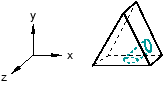
To cut the desired hole, first use the Datum toolset to create a datum plane on the Y–Z principal plane, as shown in Figure 3.
Figure 3. A datum plane.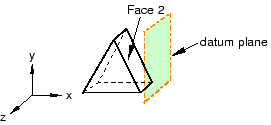
Second, sketch the profile of the cut on the new datum plane, as shown in Figure 4.
Figure 4. A sketch on the datum plane.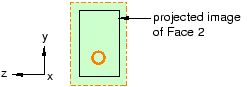
When you exit the Sketcher, Abaqus/CAE cuts the sketched hole through the part, perpendicular to the datum plane and parallel to the X-axis. This cut is illustrated in Figure 5.
Figure 5. The desired cut.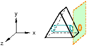
- Datum axis
You can use the Datum toolset to create a datum axis. You can then select the datum axis to control the orientation of the part on the Sketcher grid when adding or modifying a feature to a three-dimensional solid. Creating a datum axis is useful when the part does not already contain the necessary axis.
For example, suppose you want to cut a slot through the part as shown in Figure 6.
Figure 6. The desired slot.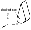
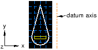
Sketching the slot is difficult because selecting either of the two straight edges of the part as the sketch's vertical axis causes the sketch gridlines to align with the line you select, not with the X- or Y-axis. To make it easier to create the slot with the desired orientation, first use the Datum toolset to create a datum axis along the Y-axis, as shown in Figure 7.
Figure 7. The datum axis.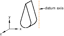
When you select the datum axis to appear vertical and on the right, the Sketcher starts, and its grid is aligned with the part's X- and Y-axes, as shown in Figure 8.
Figure 8. The resulting sketch orientation.