Defining connecting sides for a bottom-up swept mesh | ||
| ||
Connecting sides for a bottom-up mesh may be a combination of geometric faces, element faces, and two-dimensional elements. Elements or element faces must be quadrilaterals, and a single connecting side cannot contain both mesh entities and geometric faces. The criteria below and the examples that follow should help you select valid connecting sides or create valid connecting sides from sides that are initially invalid:
Each geometric face must have four logical sides.
The corners of each geometric face must be consistent with the mesh sweeping operation.
Connecting sides must share a common edge with the source side.
Geometric faces or mesh entities must form a regular grid pattern.
- Each geometric face must have four logical sides
In Figure 1 the top face contains a hole and the front face includes a triangular face. Neither face can be used as a connecting side because of these additional features.
Figure 1. Connecting sides must have four logical sides.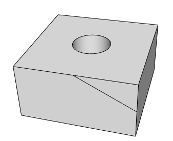
If you select sides such as these, Abaqus/CAE will display an error message indicating that the faces are topologically not four-sided.
In addition to topological tests, Abaqus applies geometric tests to determine whether faces that have four or more edges should be considered four-sided. The geometric tests evaluate the angles at the vertices of the face and determine whether a good quality structured mesh can be generated. You can override the geometric tests by using the mesh controls to assign the structured meshing technique to these faces.
For example, in Figure 2 the front face is topologically four-sided; however, because the sides meet the top edge along a curve, Abaqus/CAE does not recognize all four of the corners.
Figure 2. Faces with corner radii may require editing for use as connecting sides.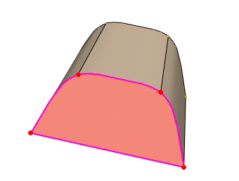
When you finish selecting connecting sides, Abaqus/CAE highlights faces that are not geometrically four-sided and displays an error message. You can use the mesh controls to redefine the region's corners as highlighted in the figure so that the face can be used as a connecting side. For more information on using mesh controls on the faces of bottom-up mesh regions, see Improving the quality of boundary meshes for a bottom-up region.
- The corners of each geometric face must be consistent with the mesh sweeping operation
The four corners shown on the selected face in Figure 3 do not match the corners of the adjacent source side (the bottom side of the part). In this case you can finish selecting the connecting sides; but when you attempt to apply the bottom-up swept mesh, Abaqus/CAE indicates that it cannot map the mesh on the connecting sides into a regular grid. If you use mesh controls to remove the corner at the semicircular cut and add a corner at the bottom left corner of the side, you can use the face as a connecting side.
Figure 3. Four-sided faces whose corners do not match the corners of the source side.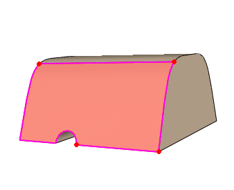
- Connecting sides must share a common edge with the source side
The common edge shared between the source side and connecting sides cannot extend beyond the edges of the source side. In addition, if you use two-dimensional elements or element faces as the source side and select geometric faces as a connecting side, or vice versa, the element edges must be associated with the geometric edge or Abaqus will not recognize them as sharing a common edge. As an alternative to associating the elements with the geometric edge, you can create a bottom-up boundary mesh on the geometric face and manually merge the nodes of the source side and connecting side meshes (for more information, see Creating the boundary mesh for a bottom-up region). If a connecting side does not share a common edge with the source side, Abaqus/CAE indicates that it cannot map the mesh on the connecting sides into a regular grid.
- Geometric faces or mesh entities must form a regular grid pattern
The geometric faces or element faces and two-dimensional elements that you select must form a regular grid pattern. Figure 4 provides two examples of acceptable connecting face patterns.
Figure 4. Acceptable connecting face patterns for swept meshing.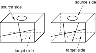
The combination of the three four-sided faces in Figure 5 makes it unacceptable as a connecting side. In this case when you indicate that you are done selecting connecting sides, Abaqus/CAE displays an error message stating that the selected geometric faces do not form a grid pattern.
Figure 5. An unacceptable face pattern.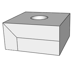
If you are unable to create acceptable connecting sides, you can leave out the connecting sides. The resulting mesh may still be acceptable for analysis. However, you should remember to associate the elements along the sides of the region with the geometry, especially if there are loads or other analysis attributes applied to the sides of the mesh. For more information, see Mesh-geometry association.