Using structured meshing near concave boundaries | ||
| ||
For example, the region in Figure 1 has five sides; therefore, when Abaqus/CAE meshes this region using the structured meshing technique, it applies the mesh pattern for a regular pentagon to the region.
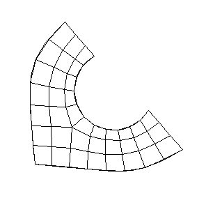
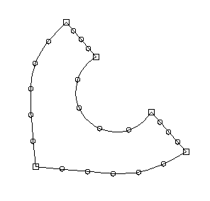
However, if you seed the region so that the number of elements is reduced, as shown in Figure 2, a distorted mesh results due to the concavity at the highly curved edge. Nodes from the interior of the mesh pattern (indicated by closed circles in Figure 3) fall outside the region's geometry, while nodes on the boundary of the mesh (indicated by open circles in Figure 3) remain on the boundary of the region's geometry.
When interior nodes fall outside the region's geometry, you can try the following techniques to improve the mesh:
Change the mesh seeds and remesh. For example, the number of elements along the highly curved edge in Figure 1 is greater than in Figure 3.
Figure 3. Nodes from the interior of the mesh fall outside the region's geometry.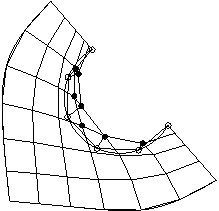
Partition the part instance into smaller, more regularly shaped regions. For example, the model was partitioned into three regions in Figure 4.
Figure 4. Partition the region.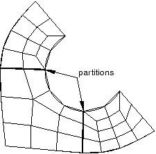
Select a different meshing technique. This option is most useful for two-dimensional regions, where you can switch from structured meshing to free meshing and still retain quadrilateral elements in the mesh. (Three-dimensional free meshing is limited to tetrahedral elements. For more information, see Free meshing.) Figure 5 shows the region meshed using the free meshing technique.
Figure 5. Mesh the region using the free meshing technique.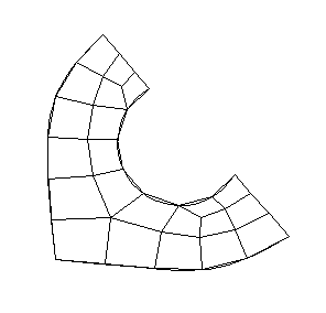
The mesh in Figure 5 is not symmetric, which is typical of free meshes.