Three-dimensional structured meshing | ||
| ||
Meshing more complex regions with this technique may require manual partitioning. If you do not partition a complex region, your only meshing option may be the free meshing technique with tetrahedral elements. Meshes constructed using the structured meshing technique consist of hexahedral elements, which are preferred over tetrahedral elements.
The characteristics described below are required to mesh a three-dimensional region successfully using the structured meshing technique:
The region cannot have any holes, isolated faces, isolated edges, or isolated vertices. For example, the regions shown in Figure 2 cannot be meshed using the structured meshing technique.
Figure 2. Regions that cannot be meshed using the structured meshing technique.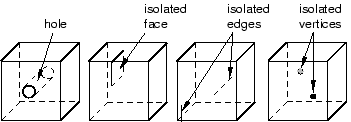
You can eliminate holes (whether they pass all the way through the part instance or just part way through) by partitioning their circumferences into halves, quarters, etc. For example, the four partitions in Figure 3 convert the part instance from one region with a hole to four regions without holes.
Figure 3. Partitions can make a part structured meshable.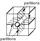
You should limit arcs to 90° or less to avoid concavities along sides and at edges. For example, the part instance in Figure 4 has been partitioned so that the single region with 180° arcs becomes two regions with 90° arcs.
Figure 4. Limit arcs to 90° or less.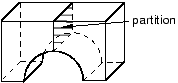
All the faces of the region must have geometries that could be meshed using the two-dimensional structured meshing technique. For example, without partitioning, the semicircles at either end of the part in Figure 5 have only two sides each. (A face must have at least three sides to be meshed using the structured meshing technique.) If you partition the part into two halves, each semicircle is divided into two faces with three sides each.
Figure 5. Partitioning creates two faces with three sides.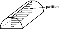
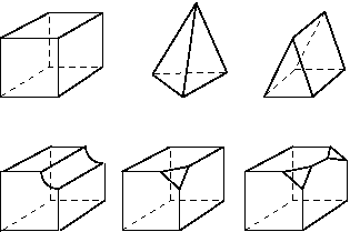
Exactly three edges of the region must meet at each vertex. For example, the vertex at the top of an unpartitioned pyramid in Figure 6 is connected to four edges. However, if you partition the pyramid into two tetrahedral regions, the vertex is connected to only three edges for each individual region.
Figure 6. After partitioning the vertex is connected to only three edges for each individual region.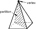
The region must be bounded by at least four sides (a tetrahedral region). If a region is bounded by fewer than four sides, you can partition the region as necessary to create additional sides.
If a region contains virtual topology, the region must be bounded by six sides.
If a region cannot be meshed using the structured meshing technique, you can use virtual topology to combine faces until the region is bounded by six sides. Figure 7 shows how you can use virtual topology to create a six-sided region that can be meshed using the structured meshing technique.
Figure 7. Virtual topology can make a part structured meshable.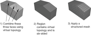
The angles between sides should be as close to 90° as possible; you should partition to eliminate angles greater than 150°.
Each side of the region must match one of the following definitions:
If the region is not a cube, a side must correspond to a single face; that is, the side must not contain multiple faces.
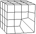
If the region is a cube, a side can be a connected set of faces that are on the same geometric surface. However, each face must have four sides. In addition, the pattern of the faces must allow rows and columns of hexahedral elements to be created in a regular grid pattern along that entire side when the cube is meshed. For example, Figure 8 shows two acceptable face patterns and the resulting regular grid pattern of elements created by meshing the cubes using the structured meshing technique.
Figure 8. Acceptable face patterns and the resulting meshes.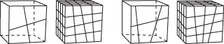
The sides in Figure 9 do not have acceptable face patterns:
Figure 9. Unacceptable face patterns.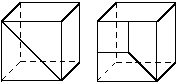
The face pattern shown on the left is unacceptable for structured meshing because each face has only three sides. Each face in the pattern shown on the right has four sides, but the pattern does not allow a regular grid of elements to be created on the partitioned side of the cube, as shown in Figure 10.
Figure 10. A regular grid of elements cannot be created.