Element type assignment | ||
| ||
Element types can be assigned to the following:
-
A region selected from geometry-based parts or part instances. The part instances must have come from parts that you created in the Part module or from parts that you imported.
-
A set that refers to a region selected from geometry-based parts or part instances. The set can also refer to a skin reinforcement.
-
An orphan element or element set.
All regions from geometry-based parts or part instances and all orphan elements have default element type assignments. These assignments depend on the kind of part to which the region or element belongs. You can view and change the Abaqus element types that are assigned using the Element Type dialog box, which you can display by selecting . For example, the Element Type dialog box for a two-dimensional structural region is shown in Figure 1.
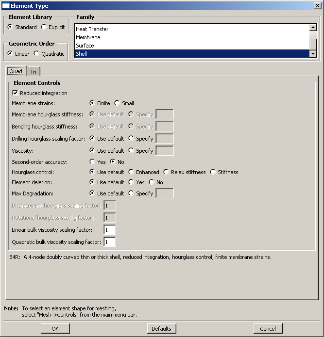
At the top of the dialog box, you enter your preferences for element library, geometric order, and family. Then, you select a specific element type by clicking the tabs in the bottom half of the dialog box and choosing from the options that appear. For more information on the element control options, see Section controls.
The dialog box can contain from one to three tabs depending on the dimensionality of the selected region or regions:
-
The Line tab allows you to choose an applicable element type and assign it to one-dimensional mesh elements in the region.
-
The Quad and Tri tabs allow you to choose an applicable element type and assign it to two-dimensional mesh elements in the region.
-
The Hex, Wedge, and Tet tabs allow you to assign three-dimensional element types to the three-dimensional mesh elements in the region.
For example, in Figure 1 the options for a linear shell element from the Abaqus/Standard element library are selected. After clicking the Quad tab, reduced integration and finite membrane strains are selected. The name and a brief description of the quadrilateral shell element that meets all of these criteria appear at the bottom of the tabbed page.
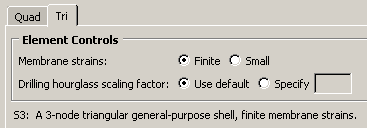
The Tri tab in this dialog box is shown in Figure 2. The name and a brief description of the triangular shell element that meets all of the criteria specified in the dialog box appear at the bottom of the Tri tabbed page in Figure 2. If the selected region in this example happens to contain a combination of triangular and quadrilateral mesh elements:
-
The quadrilateral mesh elements are assigned the S4R element type.
-
The triangular mesh elements are assigned the S3 element type.
If the region contains only quadrilateral elements, all of the elements are assigned the S4R element type.
For detailed, step-by-step instructions for assigning element types to a mesh region, see Associating Abaqus elements with mesh regions. For lists of the element types that are available, see the Abaqus/Standard Element Index and the Abaqus/Explicit Element Index. You can select most of these elements through the Element Type dialog box. What kinds of elements must be generated outside the Mesh module? describes the elements that cannot be selected.