Additional criteria for defining contact pairs | ||
| ||
- Extending surfaces
-
By default, any surface identified by the contact detection tool is extended to include adjacent model faces within 20°, even if the adjacent faces do not meet the separation and orientation requirements. The 20° angle is measured as the offset between the normals of the detected surface and the adjacent face at the common edge. You can modify the extension angle using the Extend each surface found by angle option. As faces are added to the surface definition, Abaqus/CAE also checks any faces adjacent to the newly added faces. Abaqus/CAE eliminates any redundant definitions if an extended surface incorporates a face from a separately defined contact pair. For example, consider extending surfaces within 20° for the model in Figure 2. Abaqus/CAE creates a single contact pair: one surface consists of face X, and the other surface consists of faces B, C, and D. Face D is within 20° of face C, which is within 20° of face B; the redundant contact pair consisting of face C and face X is eliminated, since it is incorporated by the larger contact pair.
- Merging contact pairs within a specified angle
-
You can use the Merge pairs when surfaces are within angle option to combine multiple contact pairs into a single definition. The faces involved in the contact pairs must be adjacent and they must lie within the specified angle (as described above). The merge option does not extend faces; it only combines positively identified contact pairs. By default, contact pairs with surfaces within 20° are merged by the contact detection tool. The merge option is typically used as an alternative to surface extension to merge contact pair candidates automatically without extending surface definitions beyond the separation tolerance. For example, merging pairs within 20° without extending surfaces for the model in Figure 2 results in a single contact pair: one surface consists of face X, and the other surface consists of faces B and C.
- Checking for surface overlap
-
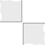
By default, the contact detection tool eliminates any contact pairs whose surfaces do not “overlap”; two surfaces do not overlap if a normal from any point on one of the surfaces does not pass through the opposing surface. For example, the surfaces in Figure 1 do not overlap, even though they may pass the separation and orientation checks.
Figure 1. Non-overlapping surfaces. The bodies are rendered in two dimensions for simplicity.
You can suppress the check for surface overlap and allow the creation of contact pairs for non-overlapping surfaces by using the Include opposing surfaces that do not overlap option.