About point-based fasteners | ||
| ||
A point-based fastener can connect selected faces with either connectors or rigid (beam) multi-point constraints. If you want to model a rigid connection, you can use rigid connectors or rigid multi-point constraints.
- Connectors
If you use connectors to connect the faces, you can model either rigid, elastic, or inelastic connections with failure by using the generality of connector behavior definitions. You can use a rigid connector to model a rigid connection. However, if you are using rigid connectors and Abaqus detects two adjacent point-based fasteners that are sharing nodes, you must avoid overconstraining your model by defining some elasticity in the connector behavior to reduce the stiffness.
You can request output from connectors.
- Rigid (beam) multi-point constraints
Rigid multi-point constraints are computationally cheaper than connectors and are less likely to result in an overconstrained model when two adjacent fasteners are sharing nodes. When Abaqus detects two adjacent fasteners that are sharing nodes and using rigid multi-point constraints, it uses a penalty distributing coupling formulation that relaxes, to a small degree, the constraint between the motion of the fastening point and its coupling nodes to avoid the overconstraint.
You cannot request output from multi-point constraints.
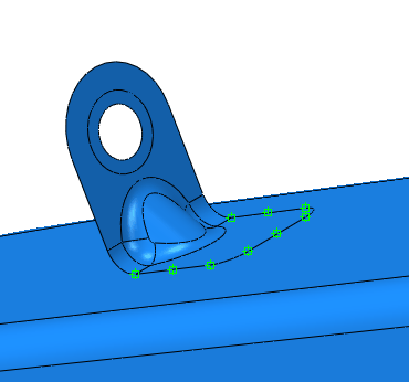
A point-based fastener uses distributing coupling constraints to connect the faces regardless of how you mesh the faces. When you submit a job for analysis, Abaqus uses your fastener definition to connect the faces with couplings and connectors. When you open the output database file in the Visualization module, you can display the couplings and connectors; however, outside the Visualization module, symbols are displayed only for the positioning points of the point-based fasteners.
If your model contains many fasteners (more than a thousand), point-based fasteners offer better performance than discrete fasteners. In addition, you may want to use point-based fasteners if you have a file from a CAD system that defines the coordinates of each positioning point. Point-based fasteners are available only for three-dimensional models. Point-based fasteners are used to model mesh-independent fasteners as described in Mesh-independent fasteners.
You can use the following two methods to create a point-based fastener, as shown in Figure 2:
Select a positioning point and allow Abaqus/CAE to project the point to the closest face along a normal to the surface. The first fastening point is created where the normal intersects the closest face.
Select a positioning point and specify the direction vector along which the point is projected. The first fastening point is created where the vector intersects the closest face.
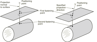
Abaqus creates the second (and subsequent) fastening points when you submit the job for analysis by projecting the first fastening point onto the other surfaces to be connected along the normal to the closest face.