The assembled fastener technique | ||
| ||
The overall process for building assembled fasteners is as follows:
-
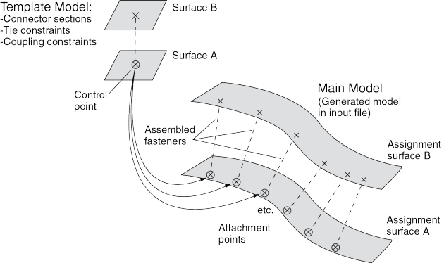
Build the template model containing your fastener-like construct: connector section assignments, tie constraints, coupling constraints, and solid or beam section assignments. You must assign names to all surfaces involved in constraints. You must also define a single-point set as the control point, which will be used to locate the template model copies in the main model.
-
Develop your main model, placing attachment points at the locations where you want the template fastener to be replicated. The template model control point will be mapped onto the locations of the attachment points in the main model (see Figure 1).
-
Working in your main model, use the Create Fasteners and Edit Fasteners dialog boxes to define how the template model will be read in, assigned, and oriented.
-
Optionally, use one or more property generation scripts to modify the properties copied into the main model from the template model. Multiple property generation scripts can be used with the same template model to achieve different results in separate assembled fastener objects. For example, you could use two scripts to apply different materials to the same fastener template. You can use the Abaqus Scripting Interface to write your property generation scripts; see Creating and running your own scripts, and the Abaqus Scripting User's Guide.
The template model uses the global coordinate system, and the positive Z-axis direction of the fastener construct will be aligned with the selected normal direction in the main model.
Assembled fasteners are different from point-based (mesh-independent) and discrete fasteners in Abaqus/CAE. Assembled fasteners do not create individual fastener objects like point-based and discrete fasteners, but instead they allow you replicate fastener-like behavior in many places. You cannot view or manipulate the individual fasteners (at each attachment point) in the main model while working in the Abaqus/CAE GUI; they are produced only in the input file generated by Abaqus/CAE. The template model sets are aggregated in the input file generated by Abaqus/CAE to help you manage models containing large numbers of assembled fasteners.
Assembled fastener template models are intended only to model fastener-like constructs and do not provide a generic subassembly capability. Only a few Abaqus/CAE features are supported in template models, such as connectors and mass inertia. No other Abaqus/CAE features are allowed in template models.
About assembled fasteners lists the features that are supported and read from the template model into the main model.
| Beam and solid parts (beam, solid, and cohesive elements) |
| Beam and solid section assignments (but not distributions or composite layups) |
| Connector section assignments |
| Tie constraints and coupling constraints (except for tie constraints generated due to incompatible meshes) |
| Adjust points constraints |
| Mass inertia |
In particular, the Abaqus/CAE features and attributes listed in About assembled fasteners are not supported by assembled fasteners and are not read in from the template model.
| Point-based (mesh-independent) and discrete fasteners |
| Attachment points |
| Analytical rigid surfaces |
| Orphan mesh surfaces |
| Tie constraints generated internally due to incompatible meshes |
| Any constraint type other than tie, coupling, or adjust points |
In addition, the following restrictions exist:
-
Solid parts are allowed in the template model but material orientations are not.
-
Beam parts are allowed in the template model, but beam orientations must be assigned using the same region as the beam section assignment.
-
Solid and beam parts are allowed, but complex parts/assemblies may not work.
-
Unmeshed constraint surfaces in the template model are allowed.
-
Shell parts are not allowed in the template model, except as reference surfaces for constraints. These constraint surfaces will effectively be replaced with main model surfaces when the input file is generated by Abaqus/CAE. All constraint surfaces should be substituted with main model surfaces for correct behavior of the assembled fastener.
-
Template model surfaces are not copied into the main model when the input file is generated by Abaqus/CAE. The only surfaces allowed in the template model are those that will have main model surfaces substituted for them.
-
Constraint surfaces cannot be orphan mesh surfaces.
-
Reference points are allowed in template models, but attachment points are not allowed.
-
The modeling space of the template models must match the modeling space of the main model (see Part modeling space).
-
Coupling constraints in the template model must constrain all degrees of freedom and must not specify a local coordinate system.
-
Tie constraints in the template model must use a generic master surface and a slave node region, not a slave surface.
-
Point mass and rotary inertia features are allowed in template models. However, for rotary inertia the local coordinate system will be ignored; thus, the only useful scenario is = = , and = = = 0. Essentially, the rotary inertia feature must have rotational symmetry.
The control point must be a predefined set containing a single vertex or node in your template model. You must create this set in the template model before creating the assembled fasteners in your main model. When the template model is read in, the control point will be placed at the locations of your attachment points in the main model.
The constraint surfaces in the template model must be mapped to corresponding surfaces in the main model to enable the constraint behavior in the main model. When you define the assembled fasteners in the main model, the Edit Fastener dialog box will automatically prepopulate the surface assignment table with any template model surfaces involved in tie constraints, coupling constraints, or adjust points constraints. The template surfaces are initially listed in ascending Z-axis order using the template model global coordinate system. You can change the order to coincide with your template fastener design; however, the ordering of the surfaces is not significant beyond the selection of the first surface, because the corresponding assignment surface normal is used to orient the assembled fastener. In the main model you must assign names to the surfaces that will be involved in the assembled fastener constraints.
At each attachment point in the main model, the template model is positioned and translated so that the template model control point coincides with the attachment point. The template model is rotated into the main model and oriented such that the positive Z-axis of the global coordinate system of the template model aligns with the coordinate system you specify (on the Orientations tabbed page of the Edit Fasteners dialog box). The default is to orient the template model copies according to the normal vector of the first surface in the main model. This default orientation from the first surface normal creates a Z-axis alignment at every attachment point. The X-axis is then computed by projecting the global X-axis onto the surface.
For any sets that you create in the template model, the main model will aggregate all of the sets' objects into a single set per assembled fastener. When the input file is generated by Abaqus/CAE, template model sets will be aggregated across all attachment points of the assembled fastener. For example, consider a template model that contains a connector section assignment for a wire set named Wire-1-Set-1, and that set contains a single wire. If the assembled fastener is then placed at 10 attachment points in the main model, the main model will have a set named TM-1_Wire-1-Set-1 that contains 10 wires. However, Abaqus/CAE generates these aggregated sets only when it creates the input file. The aggregated sets are not directly visible in Abaqus/CAE.
Note:
The Adjust control point to lie on surface option can be useful in coupling constraints you create in assembled fastener template models; see Defining coupling constraints. The more general-purpose adjust points constraint can also be useful in assembled fastener template models; see Defining adjust points constraints.
The adjust points capability should not be used in assembled fastener template models when the main model attachment points are located at bolt hole center points. Any point along the bolt hole centerline will be moved (incorrectly) to a random location along the perimeter of the hole instead of being projected along the surface normal to the center of the hole.
Note: The size and shape of the template model surfaces do not matter, except with regard to the display of those surfaces during template model rendering from the Edit Fasteners dialog box. The recommended best practice is to make your template model surfaces square or rectangular in shape to facilitate rendering speed and accuracy in the main model. Circular template model surfaces or surfaces with any curvature will be rendered in a crudely approximate fashion in the main model.