The extended finite element method (XFEM) | ||
| ||
To perform an XFEM crack analysis, you must specify the following:
- Crack domain
-
To define the crack domain, you can select one or more cells from three-dimensional parts or one or more faces from two-dimensional planar parts. If you are defining the crack domain on an orphan mesh or a part containing both orphan and native mesh elements, you can select elements. The crack domain includes regions that contain any existing cracks and regions in which a crack might be initiated and into which a crack might propagate.
- Crack growth
-
You can allow the crack to propagate along an arbitrary, solution-dependent path, or you can specify that the crack is stationary.
- Initial crack location
-
To define the initial crack location, you can select faces from a three-dimensional solid or edges from a two-dimensional planar model. The initial crack location must be contained within the crack domain. A selected face can be a face of the solid, a face created by a partition, or a planar part instance. Similarly, a selected edge can be an edge of the solid, an edge created by a partition, or a wire part instance; you should not select a seam crack. You should not mesh the faces or edges that you selected to define the initial crack location. Figure 1 shows examples of the crack domain and the crack location for two- and three-dimensional geometry and orphan meshes.
Figure 1. Defining a crack for XFEM.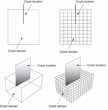
Alternatively, you can choose not to define the initial crack location. Regardless of whether you define the initial crack location, Abaqus initiates the creation of cracks during the simulation by searching for regions that are experiencing principal stresses and/or strains greater than the maximum damage values specified by the traction-separation laws.
- Enrichment radius
-
The enrichment radius is a small radius from the crack tip within which the elements will be used for calculating crack singularity for a stationary crack. Elements within the enrichment radius must be included in the cells or faces that you chose to represent the crack domain. You can allow Abaqus to calculate the radius (three times the typical element characteristic length in the enriched area), or you can specify its value.
- Contact interaction property
-
You can choose to associate a contact interaction property with the XFEM crack that defines the contact of cracked element surfaces. For detailed information, see Specifying a contact interaction property for XFEM.
- Damage initiation
-
You must specify the conditions that will initiate a crack by specifying damage initiation criteria in the material definition. You can specify a criterion based on either maximum principal stress or maximum principal strain. For more information, see Maximum principal stress or strain damage.
- Analysis procedure
-
You can include an XFEM crack in a static analysis procedure. Alternatively, you can include an XFEM crack in an implicit dynamic analysis procedure to simulate the fracture and failure in a structure under high-speed impact loading. The XFEM-based crack propagation simulated in an implicit dynamic procedure can also be preceded or followed by a static procedure to model the damage and failure throughout the loading history.
For detailed instructions, see Creating an XFEM crack.