What is a seam? | ||
| ||
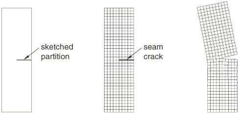
Figure 1 shows a seam on the face of a planar part and the effect of applying a tensile load to the model. The duplicate nodes along the seam are independent of each other and are free to move.

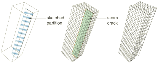
Figure 2 shows a similar analysis of a seam embedded in a solid part. The seam was created by partitioning the solid with a sketch drawn on a datum plane.

For detailed instructions, see Creating a seam, .