Defining the crack front | ||
| ||
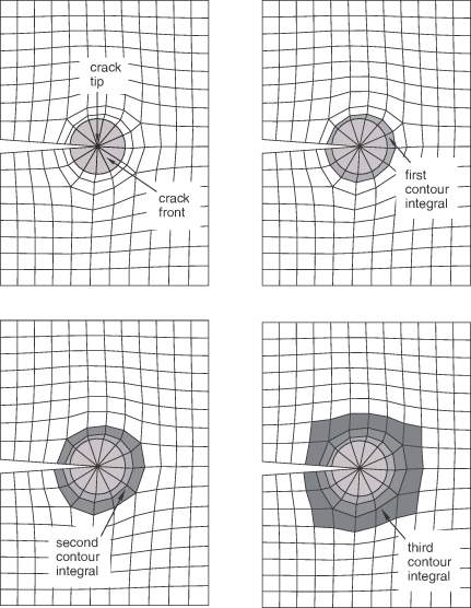
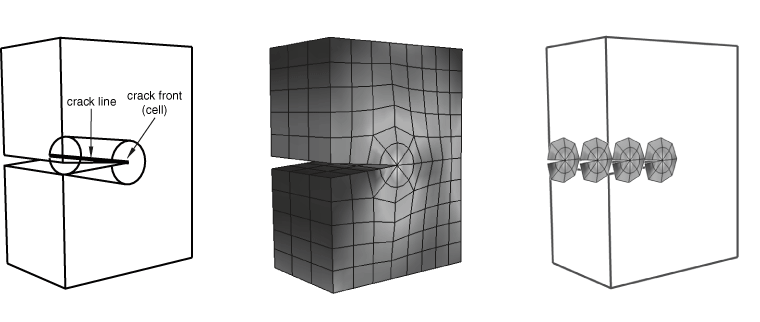
If your part is three-dimensional, Abaqus computes contour integrals at each node along the crack line, as shown in Figure 2. For more information, see Defining the crack front.
The entities from which you can select depend on whether the crack front is located in geometry or an orphan mesh and on the modeling space of the part.
- Geometry
When you are defining the crack front on geometry, the entities that you can select depend on the modeling space of the part.
- Two-dimensional geometry
If you are defining the crack front on two-dimensional geometry, you can select the following:
A single vertex
Connected edges
Connected faces
Figure 3 shows the entities from which you can select when defining a crack front on two-dimensional geometry.
Figure 3. Selecting the crack front from two-dimensional geometry.
- Three-dimensional geometry
If you are defining the crack front on three-dimensional geometry, you can select the following:
Connected edges
Connected faces
Connected cells
Figure 4 shows the entities from which you can select when defining a crack front on three-dimensional geometry.
Figure 4. Selecting the crack front from three-dimensional geometry.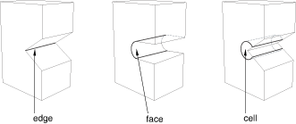
- Mesh
When you are defining the crack front on an orphan mesh, you can select the elements or element edges or faces that define the crack front. Alternatively, you can select the nodes from the corresponding region. When you are defining the crack front on an orphan mesh, the entities that you can select depend on the modeling space of the part.
- Two-dimensional orphan mesh
If you are defining the crack front on a two-dimensional orphan mesh, you can select the following:
A single node
Connected element edges
Connected elements
Figure 5 shows the entities from which you can select when defining a crack front on a two-dimensional orphan mesh.
Figure 5. Selecting the crack front from a two-dimensional orphan mesh.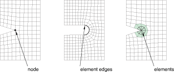
- Three-dimensional orphan mesh
If you are defining the crack front on a three-dimensional orphan mesh, you can select the following:
Connected element edges
Connected element faces
Connected elements
Figure 6 shows the entities from which you can select when defining a crack front on a three-dimensional orphan mesh.
Figure 6. Selecting the crack front from a three-dimensional orphan mesh.