Defining the crack extension direction | ||
| ||
- Normal to crack plane
If you select , you can define the normal by selecting points from the model that represent the start and the end of the normal to the crack plane. The crack plane contains the vector that Abaqus needs to compute the contour integral. In many cases the crack plane represents the plane of symmetry of the crack.
You should define the normal to the crack plane only if the direction is the same at all points along the crack line. If the direction of the normal to the crack plane varies along the crack line, you cannot select a single normal that defines the crack extension direction at all points along the crack line.
To define the normal to the crack plane, you can select points from geometry (such as vertices, datum points, or midpoints), or you can select orphan mesh nodes. Alternatively, you can enter the coordinates of the points in the prompt area. If you select points from geometry and subsequently modify the part, Abaqus/CAE regenerates the points and updates the normal accordingly. If you are working with orphan mesh nodes, you must select nodes that represent the start and the end of the normal.
Abaqus calculates a crack extension direction, , that is orthogonal to the crack front tangent, , and the normal, . If required, you can flip the -direction vector.
- q vectors
If you select , you can define the crack extension direction, , directly by selecting points from the model that represent the start and end of the vector. If you are working with orphan mesh nodes, you must select nodes that represent the start and the end of the vector. Alternatively, you can enter the coordinates of the points in the prompt area.
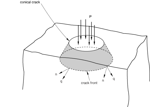
Figure 1 shows an example of a crack front formed by a circular arc along which the direction of the vector is constantly varying. In contrast, the normal to the crack plane is constant. As a result, for this case you should define the crack extension direction by specifying the normal to the crack plane.
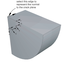
Figure 2 shows a crack front formed by the edge of a truncated cone along which the directions of both the vector and the normal to the crack plane are varying.
For this case you should do the following:
Define the contour integral, and use a single vector to specify the crack extension direction.
Mesh the part, create a job, and write the model to an input file.
Import the input file, which will create an orphan mesh representation of the part.
Edit the crack that was imported with the model. Each node along the crack front will have the crack extension direction defined by the vector that you specified in Step 1.
Use the Query toolset to determine the start and end coordinates of the vector at each node, and edit the data defining the vectors at each node along the crack front.
This technique is shown in Figure 3.
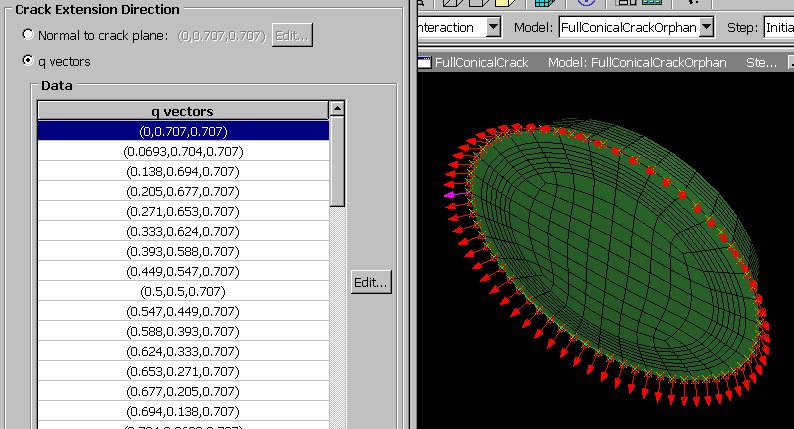
Figure 3 is taken from Contour integrals for a conical crack in a linear elastic infinite half space. An Abaqus Scripting Interface script is provided with this example that illustrates how you can enter the vector at each node along the crack front.