Manipulating the mesh | ||
| ||
Create layers of solid elements that are offset normal to selected element faces of an existing mesh, as shown in Figure 1. This tool is useful for meshing shell-like parts with solid elements. You can specify the total thickness of all the layers and the number of layers to create. The first layer of elements can be merged with the existing elements, or it can be offset by a specified distance. The selected element faces can be from either shell or solid elements, but not from both. If you selected shell element faces, you can choose whether to delete the shell elements after Abaqus/CAE generates the layers of solid elements.
Figure 1. Creating layers of solid elements.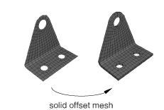
You should use this tool to generate continuum shell and cohesive elements, because the solid elements that Abaqus/CAE generates are stacked normal to the surface from which they were offset.
Create layers of shell elements that are offset normal to selected element faces from an existing mesh, as shown in Figure 2.
Figure 2. Creating layers of shell elements.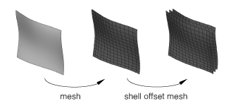
This tool is similar to the previous tool; however, instead of specifying the total thickness of the layers, you specify the distance between the layers. You should use this tool to create an offset copy of an existing shell mesh and to create multi-layered composite models or reinforcements.
Wrap a mesh. You can wrap a planar orphan mesh about the global Z-axis at a specified radius. The wrapping procedure will relocate a node at point (, ) on the planar mesh to (), where is the specified radius, = , and =.
Collapse edges. You can specify the minimum element edge size desired in the mesh. Abaqus/CAE merges the end nodes of element edges that are shorter than the specified length. By default, Abaqus/CAE checks all element edges in a mesh part, but you can specify a different element domain.
For structured meshes you can specify a thickness direction or reference edge to limit the edge directions considered for collapse. If you select a thickness direction, Abaqus/CAE uses the direction vector to measure the elements instead of measuring only the distance between nodes. If elements are oriented such that the direction is topologically ambiguous, Abaqus/CAE highlights the elements so you can either select a domain that excludes them or add a reference edge to further define the desired edges. When you choose a reference edge, with or without a thickness direction, Abaqus/CAE considers edges for collapse only if they are topologically parallel to the reference edge. A reference edge can be applied only within a single section of structured mesh; multiple separate sections must be handled in separate collapse operations if reference edges are required.
You cannot collapse small edges in an element domain that contains quadratic elements.
Grow edges. You can specify the minimum element edge size that you want to appear in the model, and Abaqus/CAE grows smaller edges to the specified minimum length by adjusting the nodes outward, effectively taking pieces from adjacent edges. Abaqus/CAE cannot increase the length of an edge if adjusting its nodes would cause the adjacent element edges to be too small. However, if you add a thickness direction, Abaqus/CAE will grow all the elements in that direction such that they will meet the minimum size.
The options for this tool are the same as those for the collapse edges tool; you can specify an element domain other than the entire mesh part, and you can use a thickness direction or a reference edge within a structured mesh to grow only those edges that meet your direction criteria. You cannot grow edges in an element domain that contains quadratic elements.
Note:
Use care when specifying an element domain other than the entire mesh. Abaqus/CAE considers for growth only those element edges within the selected domain. If short element edges exist near the border of the domain, Abaqus/CAE does not check the length of adjacent edges outside the domain before growing the ones inside the domain. Growth of edges at the domain border could result in short edges or inverted elements outside the domain.
Convert triangular elements to tetrahedral elements. You can convert a closed three-dimensional shell of triangular elements into a solid mesh of tetrahedral elements. The triangular shell elements must completely enclose a volume that can be filled with solid elements.
Convert solid orphan mesh elements to shell orphan mesh elements. This tool creates triangular or quadrilateral shell elements on the free faces of the part. For mesh parts with unmerged nodes that create crack features or mesh parts that have joined faces with incompatible meshes, Abaqus/CAE creates shell elements on both sides of the interface.
Merge layers. You can select a group of adjacent elements and join them along a specified direction. Each merged element will have the combined shape of the parent elements and the same element type. After selecting the elements to merge, you choose an edge within the elements to be merged to indicate the merge direction, as shown on the left in Figure 3. The top two layers of elements were selected using the by topology selection method (for more information, see Using the topology method to select multiple elements); for clarity the selection is not shown in the figure.
Figure 3. Merging element layers.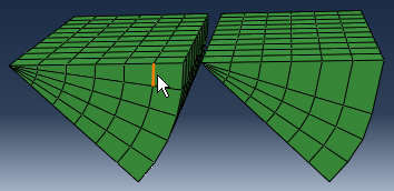
You need not select entire layers of elements to merge. However, if you do not select entire layers, Abaqus/CAE will warn you that the new elements will be incompatible with the surrounding mesh. You can then choose to continue or cancel the merge procedure. You cannot merge quadratic elements.
Subdivide layers. You can select a group of elements and split them by equally dividing the element edges. Abaqus/CAE prompts you to select an edge, a face, or to indicate the direction along which the new layers will be created and enter the number of divisions to make from each element edge. You cannot subdivide quadratic elements.
Copy a mesh pattern. You can apply a two-dimensional mesh pattern to a similar geometric target on the same part or assembly. After selecting the source mesh and target geometry, you select several nodes and map them to points on the geometry, then Abaqus/CAE finishes the mapping process to apply the mesh pattern to the target.
Associate mesh with geometry. You can associate orphan or bottom-up mesh entities with a selected geometric entity. Abaqus/CAE prompts you to select a vertex, edge, or face, and then select the node, element edges, or element faces to associate with the geometry. Association can be used to apply loads to a mesh or to create a compatible mesh at the interface between orphan mesh elements and geometry.
Delete mesh association. You can delete the mesh-geometry association for vertices, edges, faces, or entire geometric regions. You can also delete the association of a native mesh to create an orphan mesh for a portion of a model.
Insert cohesive seams. You can open pairs of connected elements at crack regions and insert a layer of pore pressure cohesive elements that are created as orphan elements in the gap region. Abaqus/CAE creates several sets and surfaces to help you make selections in subsequent procedures, such as section assignment.
| Tip: The Mesh Edit Undo feature can roll back any change you make to the mesh. For more information, see Undoing or redoing a change in the Edit Mesh toolset. |
In addition, Changing the labels of all nodes and elements, describes how you can renumber all of the nodes and/or elements of a part or selected part instances in the assembly.
For detailed instructions about manipulating the mesh, see Editing the entire mesh.