Merging and cutting part instances | ||
| ||
- Merge
You can select multiple part instances and merge them into a single part instance. For example, Figure 1 shows two part instances that model a 15-pin connector. The two part instances are positioned along a common face and then merged into a single part instance that can be meshed and analyzed.
Figure 1. Two part instances merged into a single part instance.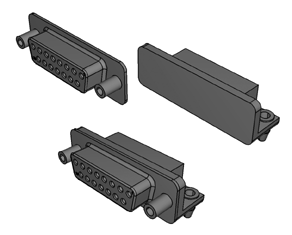
You can merge part instances even if the instances are not touching or overlapping. You can choose whether to remove or retain the intersecting boundaries between the merged part instances, as shown in Figure 2. If desired, you can use the Part Copy dialog box to create a mirror image of a part about one of the three principal planes. For more information, see Copying a part.
Figure 2. The effect of removing and retaining intersecting boundaries.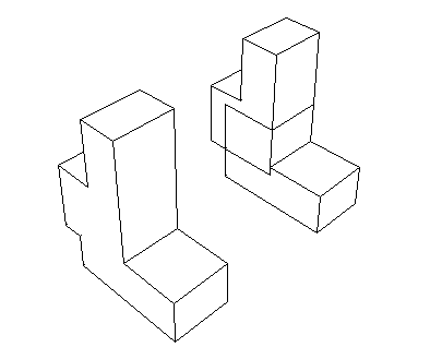
If you merge meshes, you can specify the Node merging tolerance, which is the maximum distance between nodes that will be merged. Abaqus/CAE creates a compatible mesh by deleting nodes that are closer than the specified distance and replacing them with a single new node. The location of the new node is the average position of the deleted nodes. If the value that you entered for the Node merging tolerance is too large, Abaqus/CAE may detect duplicate nodes from the same element. Abaqus/CAE will not merge nodes from the same element. However, the large tolerance can result in a distorted mesh, and Abaqus/CAE asks if you want to continue or end the merging procedure. If no nodes are closer than the specified distance, Abaqus/CAE asks if you want to cancel the procedure or to create a single instance from the selected instances.
When you merge meshed part instances that intersect, you can choose whether to create duplicate elements as well as duplicate nodes. A duplicate element has the same connectivity as another element. By default, Abaqus/CAE deletes duplicate elements, and in most cases you should accept the default behavior. However, you must retain duplicate elements if you want to model a material with a combination of material properties that are not supported by Abaqus, as described in the discussion of stability in No compression or no tension.
You can choose between the following methods for merging the nodes:
- Boundary only
By default, Abaqus/CAE merges the meshed part instances only along their boundaries (defined by free faces for three-dimensional instances and by free edges for two-dimensional instances). Free faces and edges are those faces and edges that belong to only one geometric entity or element. Using this setting, Abaqus/CAE does not check for duplicate nodes in the interior of the parts, which speeds up the merging process. You should retain this default setting if three-dimensional part instances intersect at only a common face or if two-dimensional instances intersect at only a common edge.
- All
If the part instances overlap, you may want to merge all the nodes in the selected part instances.
- None
Alternatively, you can choose to merge none of the nodes, in which case Abaqus/CAE merges the part instances into a single instance but retains all the original nodes.
In many cases you will be merging part instances that do not intersect but share a common face; for example, the two part instances shown in Figure 3.
Figure 3. Two meshed part instances merged into a single meshed part instance.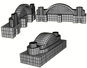
You can also merge selected nodes of a meshed part using the Edit Mesh toolset; for more information, see Manipulating nodes.
Although the resulting merged mesh may appear acceptable in the viewport, the mesh may contain small gaps between a node and an element face that are not readily apparent. The mesh may also contain merged faces that have an incompatible mesh pattern. You can use the Mesh gaps/intersections tool in the Query toolset to check for small gaps and incompatible faces. For more information, see Obtaining general information about the model.
When you merge part instances, any sets or surfaces on the original parts and part instances are mapped to the new part and part instance. If sets or surfaces from different parts have the same name, they are merged into a single set or surface on the merged part and part instance. If you choose to remove intersecting boundaries between the merged part instances, portions of sets or surfaces that lie on those boundary edges and faces are removed from the mapped sets and surfaces.
Section assignments from the original parts are also mapped to the new part. If parts in the original assembly intersect, Abaqus/CAE can map only a single section in the intersecting regions. Similarly, if parts are exactly touching or intersecting and the intersecting boundaries are removed during the merge, Abaqus/CAE maps only a single section to the entire merged part. In these intersecting situations, the section that gets mapped is dependent on a variety of factors and may not match your modeling intent. When merging intersecting regions, you should retain the intersecting boundaries; the boundaries preserve the original section assignments in nonintersecting regions and make it easier to modify mapped section assignments if necessary (for details, see Managing section assignments).
Note:
Beam section assignments and rebar reference orientations are not mapped to the merged part. You must recreate them and any associated properties after the merge.
You might want to merge part instances for the following reasons:
If geometry in separate instances touches or overlaps but you do not merge the instances, Abaqus/CAE creates a separate mesh for each instance and you must apply tie constraints to effectively merge the nodes. In contrast, when you merge part instances, Abaqus/CAE creates a single combined mesh and you do not need to apply computationally expensive tie constraints. In effect, you have created a compatible mesh between the part instances. If you want to retain the concept of separate part instances, you can create partitions at the common interface of the merged instances.
Merging part instances allows you to assign material properties to the single part created by the merge operation instead of to each part individually.
You can apply a display body constraint to a group of merged part instances instead of applying the constraint to each part instance individually.
When you import a complex assembly, the assembly may appear in Abaqus/CAE as a large number of individual part instances that will be meshed individually. You can merge all the part instances into a single part instance, or you can merge groups of part instances into several separate part instances.
You have the following three options when merging part instances:
- Geometry
Merge only the geometry. Any orphan mesh portions of the instances being merged are deleted from the merged part and part instance.
- Mesh
Merge all native and orphan mesh components. Any geometry of the instances being merged is deleted from the merged part and part instance. The native mesh portion of the original parts becomes part of the orphan mesh in the new part.
- Both
Merge both the geometry and the orphan mesh. Any native meshes are deleted in the process of merging the geometry.
- Cut
You can select the geometric portion of a single part instance to be cut, and then you can select the geometry of one or more part instances that are touching or overlapping the part instance to be cut. Abaqus/CAE uses the geometry that will make the cut (the die) to cut away from the geometry of the instance to be cut (the blank). Geometry must touch or overlap to create a cut part and part instance. If the part instance being cut includes orphan mesh elements, they are unaffected by the cut operation.
When you cut a part instance, sets, surfaces, and section assignments from the original part and part instance are mapped to the new part and part instance. Portions of original sets and surfaces that lie within cut portions of the original geometry are removed from the mapped sets and surfaces.
The cut operation is useful if you want to create a mold from a part or vice versa. Figure 4 shows a bottle and a rectangular blank and how the cut process creates the mold.
Figure 4. A mold created from a blank and a die using the cut operation.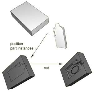
You cannot make a cut with a shell part instance. Therefore, before the cut operation was performed, the bottle was converted from a shell to a solid part in the Part module. For more information, see Creating a solid feature from a shell. In addition, the original part instances (the blank and the die) were suppressed after the cut operation. The cut operation is also useful for modeling a structure and an acoustic medium when you are performing an acoustic or shock analysis.
Note:
You cannot merge or cut part instances that contain virtual topology.