Positioning a part or model instance using the Translate To tool | ||
| ||
When you use the Translate To tool to position instances in three-dimensional modeling space, you select faces to come into contact; for instances in two-dimensional or axisymmetric modeling space, you select edges to come into contact. In addition, when you use the Translate To tool to position axisymmetric instances, the translation vector must be parallel to the axis of revolution.
When you use the Translate To positioning tool, you can select more than one face or edge from both the fixed and the movable instances. Selecting multiple faces or edges is useful if you are not sure what part of the model will come in contact when the movable instance moves along the selected vector. However, for faster processing you should select as few faces or edges as possible.
To translate a movable part or model instance to a fixed instance, you do the following:
Select faces or edges from the instance that will move and from the instance that will remain stationary.
Prescribe the motion of the movable instance by defining a translation vector. Figure 1 illustrates the selected edges and translation vector.
Figure 1. Select the edges to contact, and define the translation vector.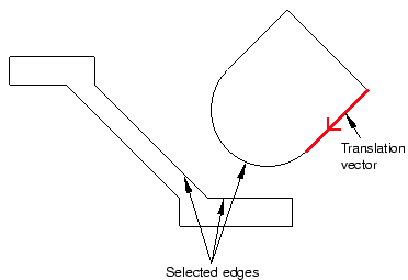
Define the desired clearance between the selected faces or edges. Figure 2 shows the effect of the contact constraint after specifying a clearance value of zero and a clearance value of d.
Figure 2. The effect of applying a contact constraint and specifying clearance values of zero and d.
To measure the clearance d, Abaqus/CAE first moves the instance along the translation vector until any pair of selected faces or edges come into contact. Abaqus/CAE then moves the instance along the translation vector a distance specified by the clearance value. The clearance can be zero or a positive or negative number; a negative value for the clearance results in overclosure between the selected faces or edges. When you use the Translate To tool, Abaqus/CAE calculates the position of the movable instance within a tolerance based on its size. If you want to avoid any possibility of overclosure, you should specify a small clearance value, rather than simply specifying zero.
Abaqus/CAE displays an error message and does not move the instance if contact between the selected faces or edges is not possible along the translation vector.
Even though you translate the movable instances until contact occurs with a fixed instance, the physical proximity of the selected surfaces is not enough to indicate any type of interaction between them. You must use the Interaction module to specify mechanical contact between surfaces. The Translate To positioning tool is satisfied only within a tolerance based on the size of your model. As a result, contact may not be precise unless it is applied between two planar surfaces.
Abaqus/CAE approximates a curved face with a set of faceted faces. Likewise, Abaqus/CAE approximates a curved edge with a set of faceted edges. The number of facets depends on the degree of curve refinement that you specified when creating the part in the Part module. Use the box zoom tool  to view the faceting applied to curved faces or edges in the assembly. When you are translating curved faces or curved edges, Abaqus/CAE computes the contact position using this faceted representation. You may wish to set the curve refinement to a finer setting based on the curvature of faces or edges that you know will be coming into contact. For more information, see Controlling curve refinement.