Using datum geometry in the Assembly module | |||||
|
| ||||
Datum geometry that you create in the Part module is transferred along with the rest of the part's geometry when you create a part instance in the Assembly module. In addition, when you translate and rotate a part instance in the Assembly module, a datum created in the Part module is translated and rotated along with the instance. In contrast, a datum created in the Assembly module follows only the reference points that were used to create the datum. As a result if you translate and rotate a part instance, the behavior of the datum may not reflect your design intent. If you know that a datum should be associated with a part, you should create the datum in the Part module.
Figure 1 illustrates a model in which a deformable curved shell will be compressed between two rigid surfaces.
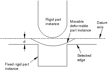
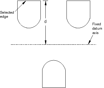
The shell is positioned easily by applying an edge-to-edge position constraint between a selected edge of the lower rigid surface (the fixed part instance) and a datum axis associated with the shell (the movable part instance). The datum axis was created with the deformable part in the Part module and moves along with the movable part instance when the position constraint is applied. In contrast, Figure 2 illustrates an edge-to-edge position constraint applied between three movable part instances and a fixed datum axis that provides reference geometry. In this example the datum axis was created along the X-axis of the assembly and is not associated with any part instance. Applying three edge-to-edge position constraints, one to each of the three part instances shown, would result in alignment of the three instances along the datum axis.
A datum is a feature of the assembly and is regenerated along with the rest of the assembly. You can make datum geometry invisible while still retaining it in the assembly by selecting from the main menu bar. For more information, see Controlling datum display.
The triad indicating the origin and the orientation of the global coordinate system is a datum coordinate system created by the Assembly module. You can suppress or delete it, but you cannot modify it.