Load case editors | ||||
|
| |||
The top panel of the load case editor displays the name of the load case and the current analysis step. The load case editor contains two tabbed pages with tables that allow you to select the loads and boundary conditions to define the load case. By default, Abaqus/CAE includes all boundary conditions propagated or modified from the base state in each load case that you create. You can toggle off this behavior on the Boundary Condition tabbed page.
Click  at the bottom of each tabbed page to select loads and boundary conditions from a list. You can enter a scale factor to scale the magnitude of individual loads and boundary conditions. If you enter a negative scale factor for a load, the load will be applied in the opposite direction. You can also enter the names of the loads and boundary conditions and the scale factors directly in the tables. During load case creation, Abaqus/CAE sorts the names of the loads and boundary conditions alphabetically and lists the names in the load case editor. You can highlight selected loads and boundary conditions in the viewport.
For example, you can define a set of load cases to analyze the response of a cantilever beam subjected to an end load and a uniform pressure load. The cantilever beam model is shown in Figure 1.
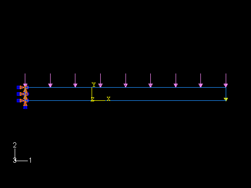
An encastre boundary condition is applied in the initial step, and the end load and pressure load are applied in a static, linear perturbation step.
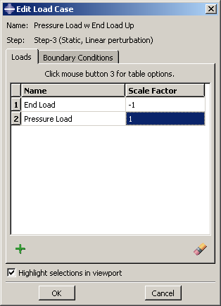
You can create a load case that contains only the end load and another that contains only the pressure load. In addition, you can create a load case that contains both the pressure load and the end load with the end load applied in the opposite direction (scale factor value of −1), as shown in Figure 2.
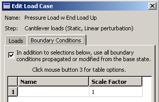
By default, each load case contains the encastre boundary condition propagated from the base state, as shown in Figure 3.
The Load Case Manager in Figure 1 shows the three load cases created for the cantilever beam model.