Creating a composite layup | ||
| ||
You create a composite layup in the Property module. The composite layup editor provides a table that you use to define the plies in the layup. For each ply you specify the ply's name, material, thickness, and orientation, as well as the number of integration points and the region of the model to which the ply is assigned. The composite layup editor's ply table is shown in Figure 1.
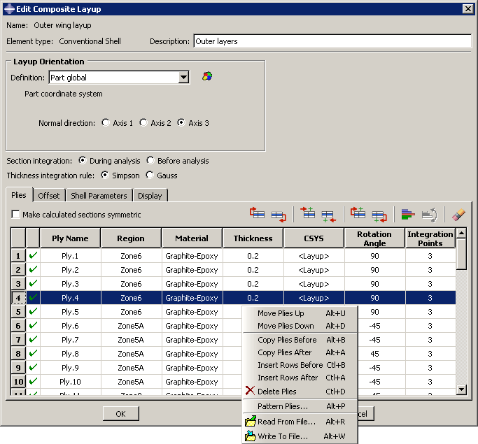
The ply table provides several options that make it easier for you to define a layup containing many plies; for example, the ply table allows you to do the following:
Move or copy selected plies up or down in the table.
Suppress or delete selected plies.
Pattern a group of selected plies.
Read ply data from or write ply data to an ASCII file. The data can define all the plies in the layup or only a subset of the plies in the layup.
The ability to suppress plies allows you to easily experiment with different configurations of plies in the composite layup and to see the effect on the results of an analysis of the model. For more information, see Using the ply table when defining a composite layup.
If you are defining a composite layup whose plies are symmetric about a central core, you only need to enter the bottom half of the layup in the ply table. When you apply the symmetry option, Abaqus automatically creates additional plies in the generated sections by repeating the entered plies (including the central ply) in reverse order.
You will probably have to partition your model to create the regions to which you will assign plies. You should create the partitions before you create the layup and start defining plies. You can select a region directly from the part in the current viewport, or you can create a named set that refers to the region and select the named set. Abaqus/CAE preserves any existing ply regions if you decide to add partitions and plies after you have defined a composite layup; for example, you can add plies to a layup that model a rib providing additional stiffness to a region. The region to which you assign a ply can be either Abaqus/CAE geometry or a mesh. You can combine plies assigned to geometry and plies assigned to a native mesh in a single composite layup.
Continuum shell and solid composite layups are expected to have a single element through the entire thickness across a combination of all the regions specified in the composite layup. Each single element through the thickness contains the multiple plies that you defined in the ply table. If the region to which you assign your continuum shell or solid composite layup contains multiple elements through the thickness, each element will contain all of the plies that you defined in the ply table and the analysis results will not be as expected.
If your model contains multiple continuum shell or solid elements through the thickness of a region, you can obtain correct results by defining a separate composite layup for each layer of elements. You can define a composite layup for each layer by selecting the elements of a native Abaqus/CAE mesh or the orphan elements when you specify the region of the layup. You must create a layup for each layer of elements.
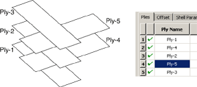
If you have plies that overlap in your composite layup, you must enter the plies in the ply table in the order that they appear in the overlapping region. Figure 2 illustrates a simple example of an overlapping region and the corresponding order of the plies in the ply table. The first ply in the ply table represents the bottom ply in the layup.
Under certain circumstances, Abaqus cannot determine the orientations of the composite ply for conventional shells. This can occur, for example, if your ply makes a sharp transition through an angle of 90°, and/or your part is aligned with one or more planes of the global coordinate system. To help you diagnose the problem region, Abaqus/CAE draws a collapsed coordinate system indicating regions for which the user-selected coordinate system and the geometric normal cannot be resolved into a valid orientation for display purposes. If this situation arises, you may be able to complete the analysis by splitting the ply into multiple plies at the transitions and by assigning orientations to each new ply.
If you apply a composite layup and assign a section assignment to the same region, Abaqus/CAE uses only the properties from the composite layup during the analysis. If you apply two or more composite layups to regions that overlap, Abaqus/CAE uses the properties of the last layup, where last refers to the alphabetical order of the names of the composite layups. The default color coding in the Property module uses yellow coloring to indicate a region with overlapping composite layups and section assignments or to indicate a region with multiple overlapping composite layups.