Crack propagation in a plate with a hole simulated using XFEM | ||
| ||
ProductsAbaqus/StandardAbaqus/CAE
Problem description
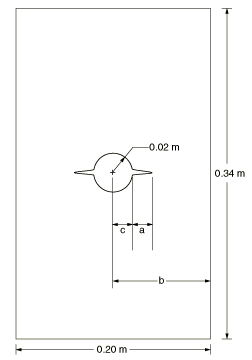
A plate with a circular hole is studied. The specimen, shown in Figure 1, has a length of 0.34 m, a thickness of 0.02 m, a width of 0.2 m, and a hole radius of 0.02 m, under pure Mode I loading. Figure 1 defines the dimensions used to calculate the variation of crack length, : a is the crack length, b is half the specimen width, and c is the hole radius.
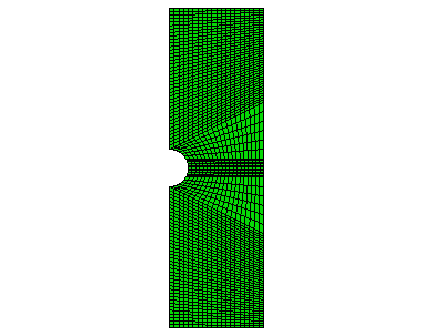
Equal and opposite displacements are applied at both ends in the longitudinal direction. The maximum displacement value is set equal to 0.00055 m. To examine the mesh sensitivity, three different mesh discretizations of the same geometry are studied. Symmetry conditions reduce the specimen to a half model. The original mesh, as depicted in Figure 2, has 2060 plane strain elements. The second mesh has four times as many elements as the original one, while the third mesh has sixteen times as many elements as the original one.
In the low-cycle fatigue analysis, two steps are involved. A static step is used to nucleate a crack at the site of stress concentration prior to the low-cycle fatigue direct cyclic step, in which a cyclic distributed loading with a peak value of 1.25 MPa is specified. Three different mesh discretizations of the same geometry are studied. The second mesh has twice as many elements as the original mesh, while the third mesh has four times as many elements as the original mesh.
The material data for the bulk material properties in the enriched elements are GPa and = 0.3.
The response of cohesive behavior in the enriched elements in the model is specified. The maximum principal stress failure criterion is selected for damage initiation, and an energy-based damage evolution law based on a BK law criterion is selected for damage propagation. The relevant material data are as follows: MPa, × 103 N/m, × 103 N/m, and . The relevant material data defined above are also used in the model simulated using the XFEM-based LEFM approach. When the low-cycle fatigue analysis using the Paris law is performed, the additional relevant data are as follows: , , × 10−6, , , and .
![]()
Results and discussion
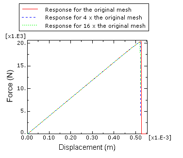
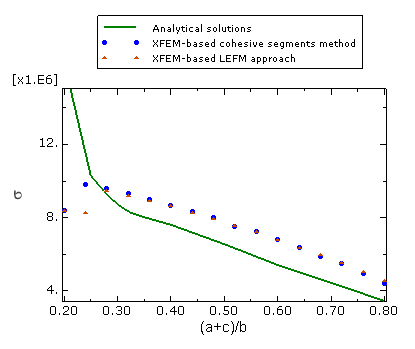
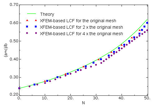
Figure 3 shows plots of the prescribed displacement versus the corresponding reaction force with different mesh discretizations when the XFEM-based cohesive segments method is used. The figure clearly illustrates the convergence of the response to the same solution with mesh refinement. A plot of the applied stress versus the variation of crack length is presented in Figure 4 and compared with the results obtained by using the XFEM-based LEFM approach as well as the analytical solution of Tada et al. (1985). The agreement is better than 10% except when the crack length is small, in which case the stress singularity ahead of the crack is not considered by the XFEM approach. However, as indicated in this figure, the crack initiates (i.e., ) when the applied stress, , reaches a level of 8.37 MPa, giving a ratio of equal to 2.63. This value is in close agreement with the stress concentration factor of 2.52 obtained analytically for the same geometry. In addition, the results in terms of crack length versus the cycle number obtained using the low-cycle fatigue criterion in Abaqus are compared with the theoretical results in Figure 5. Reasonably good agreement is obtained.
![]()
Input files
- crackprop_hole_xfem_cpe4.inp
Abaqus/Standard two-dimensional plane strain model with a hole under pure Mode I loading simulated using the XFEM-based cohesive segments method.
- crackprop_hole_xfem_dload_cpe4.inp
Same as crackprop_hole_xfem_cpe4.inp but with distributed pressure loads.
- crackprop_hole_xfem_dload_user_cpe4.inp
Same as crackprop_hole_xfem_cpe4.inp but with user-defined distributed pressure loads.
- crackprop_hole_xfem_dload_user_cpe4.f
Subroutine for user-defined distributed pressure loads.
- crackprop_hole_lefm_xfem_cpe4.inp
Abaqus/Standard two-dimensional plane strain model with a hole under pure Mode I loading simulated using the XFEM-based LEFM approach.
- crackprop_hole_xfem_cpe4_user.inp
Same as crackprop_hole_xfem_cpe4.inp but with user-defined damage initiation criterion.
- crackprop_maxps_quads_xfem_udmgini.f
Subroutine for a user-defined damage initiation criterion with two different failure mechanisms.
- crackprop_hole_fatigue_xfem_cpe4.inp
Same as crackprop_hole_lefm_xfem_cpe4.inp but subjected to cyclic distributed loading.
- crackprop_hole_fatigue_xfem_cpe4_2.inp
Same as crackprop_hole_fatigue_xfem_cpe4.inp but with twice as many elements.
- crackprop_hole_fatigue_xfem_cpe4_3.inp
Same as crackprop_hole_fatigue_xfem_cpe4.inp but with four times as many elements.
![]()
Python scripts
- crackprop_hole_xfem_cpe4.py
Script to generate the two-dimensional plane strain model with a hole under pure Mode I loading in Abaqus/CAE simulated using the XFEM-based cohesive segments method.
- crackprop_hole_lefm_xfem_cpe4.py
Script to generate the two-dimensional plane strain model with a hole under pure Mode I loading in Abaqus/CAE simulated using the XFEM-based LEFM approach.
![]()
References
- “The Stress Analysis of Cracks Handbook, 2nd Edition,” Paris Productions Incorporated, 226 Woodbourne Drive, St. Louis, Missouri, 63105, 1985.
![]()
Figures