Revolute MPC verification: rotation of a crank | ||
| ||
ProductsAbaqus/Standard
Problem description
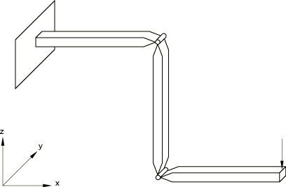
Figure 1 shows the model after the revolutes have been rotated to create a crank. The crank is made of three segments, each 400 mm long. Initially they all lie along the global x-axis. The segments all have the same square cross-section, 20.3 mm × 20.3 mm, and are made of a material with a Young's modulus of 200 GPa and Poisson's ratio 0.0. The segments are connected by revolute joints whose axes are initially parallel to the global y-axis.
The segments of the crank are modeled with element type B31H. This “hybrid” beam element formulation is chosen because it provides rapid convergence of the nonlinear solution in cases of relatively stiff members undergoing large angular motions. The revolute joints are modeled with REVOLUTE MPCs (General multi-point constraints). This requires separate nodes for the two sides of each joint and a third node for use in defining the revolute axis. Degree of freedom 6 at the third node represents the relative rotation in the joint. The line between the second and third nodes defines the initial direction of the axis of the joint.
![]()
Loading
The crank is built-in at one end. The revolutes are initially locked, and a load of −498.2 N is applied to the free end of the crank in the z-direction. The revolute joints are then subjected to opposing internal rotations of magnitude /2, thus creating the crank-like geometry shown in Figure 1. Finally, the entire crank is rotated through an angle of /2 about the global z-axis.
![]()
Results and discussion
The analysis includes an initial linear perturbation step in which the straight crank is loaded without considering geometric nonlinearity. This step is introduced mainly for verification of the model. Simple beam theory shows that the tip deflection at the end of the first step should be 107.95 mm. The analysis gives a value of 106.8 mm. The same loading with geometric nonlinearity included gives a tip displacement of 105.9 mm—slightly less because the bending of the beam in this case stiffens its response.
In the next step relative rotations are applied in the joints to make the bar into a crank, while the load remains on the tip. The 90° rotation is applied in four increments by prescribing the value of degree of freedom 6 at the relative rotation nodes (nodes 12 and 14). For comparison, we analyze a crank made with B31H elements with rigid joints. The tip displacement of 40.64 mm obtained in this analysis agrees exactly with that provided by the analysis with the revolutes, when the 400 mm displacement caused by the revolute rotation is taken into consideration.
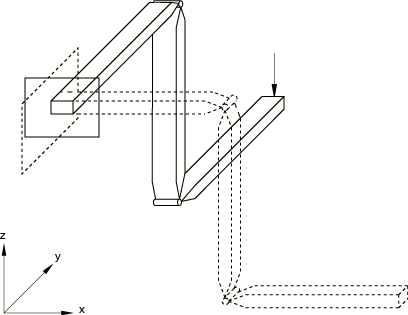
The last step rotates the entire crank by 90° about the global z-axis. This is accomplished in four increments. The final configuration is shown in Figure 2.
![]()
Input files
- revolutempc_joints.inp
-
Crank with revolute joints.
- revolutempc.inp
-
Crank without revolute joints.
![]()
Figures