LE3: Hemispherical shell with point loads | ||
| ||
ProductsAbaqus/StandardAbaqus/Explicit
Elements tested
- S3
- S3R
- S4
- S4R
- S4R5
- S8R
- S8R5
- S9R5
- STRI3
- STRI65
- SC6R
- SC8R
- SAXA12
- SAXA22
![]()
Problem description

Model:
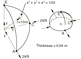
The model is illustrated in the figure above. In addition, two input files are provided for the continuum shell element model to illustrate the use of the STACK DIRECTION=ORIENTATION parameter to define the element thickness (stacking) direction independent of the nodal connectivity using a spherical system.
Material:
Linear elastic, Young's modulus = 68.25 GPa, Poisson's ratio = 0.3.
Boundary conditions:
0 at point E. Along edge AE, symmetry about the z–x plane. Along edge CE, symmetry about the y–z plane.
Loading:
Concentrated radial loads of 2 kN outward at A, inward at C.
![]()
Reference solution
This is a test recommended by the National Agency for Finite Element Methods and Standards (U.K.): Test LE3 from NAFEMS publication TNSB, Rev. 3, “The Standard NAFEMS Benchmarks,” October 1990.
Target solution: 185 mm at point A.
![]()
Results and discussion
The values enclosed in parentheses are percentage differences with respect to the reference solution.
| Element | at A (Coarse) | at A (Fine) |
|---|---|---|
| S3/S3R | 0.080 (−57%) | 0.161 (−13%) |
| S4 | 0.083 (−55%) | 0.175 (−5%) |
| S4R | 0.180 (−2.7%) | 0.180 (−2.7%) |
| S4R* | 0.072 (−61%) | 0.170 (−8.1%) |
| S4R** | 0.058 (–68%) | 0.168 (–9.1%) |
| S4R5 | 0.190 (2.7%) | 0.183 (−1.1%) |
| S8R | 0.101 (−45%) | 0.178 (−3.8%) |
| S8R5 | 0.179 (−3.2%) | 0.185 (0.0%) |
| S9R5 | 0.179 (−3.2%) | 0.185 (0.0%) |
| STRI3 | 0.173 (−1.2%) | 0.185 (0.0%) |
| STRI65 | 0.169 (−8.6%) | 0.182 (−1.6%) |
| SC6R | 0.088 (−52.4%) | 0.167 (−9.7%) |
| SC8R | 0.210 (13.5%) | 0.188 (1.6%) |
| SC8R*** | 0.194(4.9%) | 0.185(0.0%) |
| SAXA12**** | 0.179 (−3.2%) | |
| SAXA22**** | 0.178 (−3.8%) |
* Abaqus/Explicit finite-strain element with enhanced hourglass control. **Abaqus/Standard finite-strain element with enhanced hourglass control. *** Abaqus/Explicit continuum shell element with the default “relax stiffness” hourglass control. **** Due to the loading position, only the Mode 2 and Mode 4 elements can be used. Furthermore, due to the symmetries of the problem, only the Fourier interpolator contributes to the solution. Thus, the Mode 4 elements produce identical results. Since Mode 4 is the highest-order Fourier term provided, no further circumferential mesh refinement is possible, and only coarse mesh results can be obtained.
The continuum shell element meshes using the STACK DIRECTION=ORIENTATION parameter yield identical results to the continuum shell element meshes in which the thickness direction is defined by the element nodal connectivity.
![]()
Input files
Abaqus/Standard input files
- nle3xf3x.inp
-
S3/S3R elements.
- nle3xe4x.inp
-
S4 elements.
- nle3xf4x.inp
-
S4R elements.
- nle3xf4x_eh.inp
-
S4R elements with enhanced hourglass control.
- nle3x54x.inp
-
S4R5 elements.
- nle3x68x.inp
-
S8R elements.
- nle3x58x.inp
-
S8R5 elements.
- nle3x59x.inp
-
S9R5 elements.
- nle3x63x.inp
-
STRI3 elements.
- nle3x56x.inp
-
STRI65 elements.
- nle3xntx.inp
-
SAXA12 elements.
- nle3xnxx.inp
-
SAXA22 elements.
- nle3_std_sc6r.inp
-
SC6R elements.
- nle3_std_sc8r.inp
-
SC8R elements.
- nle3_std_sc6r_stackdir_sphori.inp
-
SC6R elements using the STACK DIRECTION=ORIENTATION parameter with a spherical orientation system to define the element thickness direction.
- nle3_std_sc8r_stackdir_sphori.inp
-
SC8R elements using the STACK DIRECTION=ORIENTATION parameter with a spherical orientation system to define the element thickness direction.
- nle3_std_sc8r_sgs.inp
-
SC8R elements using SHELL GENERAL SECTION to define section properties.
Abaqus/Explicit input files
- le3_s4r.inp
-
S4R elements with enhanced hourglass control.
- le3_sc8r.inp
-
SC8R elements with the default “relax stiffness” hourglass control.