Deflection of an elastic dam under water pressure | ||
| ||
ProductsAbaqus/ExplicitAbaqus/CAE
Problem description
In the initial configuration of the model, water is located in a rectangular reservoir. The floor and right side of the reservoir are fixed. On the left side the water is contained by an elastic dam wall; the top half of the dam is fixed, but the bottom half is unconstrained. Under a gravity load the water pushes against the dam, deflects the bottom portion of the dam, and flows freely out of the reservoir.
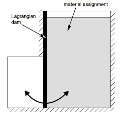
The model is created in Abaqus/CAE using two parts. An Eulerian part represents the domain within which the water will flow. A Lagrangian part represents the dam. The problem is essentially two-dimensional with horizontal (X-direction) and vertical (Z-direction) components; but because Eulerian elements must be three-dimensional, all parts are modeled with a thickness in the Y-direction equivalent to one Eulerian element.
The Eulerian part is shown in Figure 1. Figure 2 shows the distribution of material within the part: the region on the right is filled with water, the region on the left is the anticipated outflow region, and the middle region contains the Lagrangian dam. Zero-velocity boundary conditions are applied normal to the floor and right side of the Eulerian part to prevent water from flowing out of these boundaries. No boundary conditions are applied along the left side of the dam; water is free to flow out of the part at this interface (which results in a corresponding decrease in total mass for the model). Zero-velocity boundary conditions are applied in the horizontal and vertical directions on the upper half of the dam, but the bottom half is free to deflect (see Figure 2). Another set of zero-velocity boundary conditions in the Y-direction are applied to each part to prevent movement out of the two-dimensional plane. A frictionless general contact definition enforces contact between the water and the dam.
The dam is modeled as an elastic material with Young's modulus of 1.2 × 10⁷ N/m2, Poisson's ratio of 0.4, and density of 1100 kg/m3. The water is defined using the linear Hugoniot form of the Mie-Grüneisen equation of state with the parameters listed in Table 1.
A gravitational load is applied to the entire model. In addition, initial geostatic stresses are defined to model the hydrostatic pressure in the water. Because geostatic stresses cannot be defined directly in Abaqus/CAE, they are added to the model using the Keywords Editor.
The Eulerian part is meshed with EC3D8R elements using a global mesh seed of 5 mm; this global mesh seed allows a uniform distribution of cube-shaped elements throughout the part, which greatly improves the accuracy of the Eulerian analysis. The dam is meshed with C3D8R elements in a grid measuring 75 × 4; there are three elements through the thickness of the part. Multiple elements through the width and thickness of the dam are necessary to ensure that its bending behavior is captured adequately.
![]()
Results and discussion
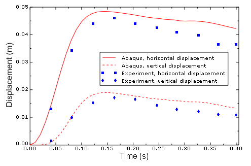
The pressure of the water under gravity deflects the bottom half of the dam, allowing water to flow out of the reservoir. Figure 3 uses an isosurface view cut based on output variable EVF_WATER to show the position of the water at six points during the analysis. The displacement in the horizontal and vertical directions of the lower-right corner of the dam can be compared to experimental results from Antoci et al. (2007), as shown in Figure 4. The Abaqus results agree well with the experimental results. Discrepancies are likely due to idealizations in the dam material model, rendering it slightly more flexible than the experimental dam. Antoci et al. also note some minor flaws in the experimental setup that could result in decreased water pressure on the dam, which in turn would lead to a lower overall deflection.
![]()
References
- “Numerical Simulation of Fluid-Structure Interaction by SPH,” Computer and Structures, vol. 85, pp. 879–890, 2007.
![]()
Tables
| Parameter | Value |
|---|---|
| Density () | 1000 kg/m3 |
| Viscosity () | 0.001 N s/m2 |
| 1500 m/s | |
| s | 0 |
| 0 |
![]()
Figures