Buckling analysis of beams | ||
| ||
ProductsAbaqus/Standard
Buckling studies such as this usually require two types of analyses.
Eigenvalue analysis is used to obtain estimates of the buckling loads and modes. The concept of eigenvalue buckling prediction is to investigate singularities in a linear perturbation of the structure's stiffness matrix. The resulting estimates will be of value in design if the linear perturbation is a realistic reflection of the structure's response before it buckles. For this to be the case, the structural response should be linear elastic. In other words, eigenvalue buckling is useful for “stiff” structures (structures that exhibit only small, elastic deformations prior to buckling). Such analysis is performed using the eigenvalue buckling procedure (Eigenvalue buckling prediction), with the “live” load applied within the step. The buckling analysis provides the factor by which the live load must be multiplied to reach the buckling load. Any preload must be added to the load from the eigenvalue buckling step to compute the total collapse load.
It is usually also necessary to consider whether the postbuckling response is stable or unstable and if the structure is imperfection sensitive. In many cases the postbuckled stiffness may not be positive. The collapse load will then depend strongly on imperfections in the original geometry (“imperfection sensitivity”). This is addressed by following the eigenvalue prediction with a load-displacement analysis of the structure. Typically this is done by assuming an imperfection in the original geometry, in the shape of the buckling mode, and studying the effect of the magnitude of that imperfection on the response. Material nonlinearity is often included in such collapse studies. This example illustrates these analyses for some simple, classical, beam problems.
Problem description
The objectives for this example include the study of buckling under the action of axial and transverse loads. Such studies are usually classified as follows:
Flexural buckling of axially compressed beams in flexural modes (Euler buckling).
Lateral buckling of beams that are loaded transversely in the plane of higher flexural rigidity. This is of importance in the design of beams without lateral supports in which the bending stiffness of the beam in the plane of loading is large in comparison with the lateral flexural rigidity. The plane configuration of the beam becomes unstable if the load is increased beyond the critical value.
Torsional buckling of beams subjected to uniform axial compression in torsional modes while their longitudinal axis remains straight. In general, torsional buckling is important for thin-walled columns having wide flanges and short lengths.
A column may buckle in any one of these modes. Only the lowest value is of practical interest in design calculations. In general cases, buckling failure may occur by a combination of torsion and bending, which is best addressed by a load-displacement study.
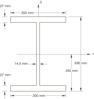
We consider slender, elastic straight beams, orientated along the x-axis, all with the I-section shown in Figure 1. The section dimensions are suitable for the study of flexural, lateral, and torsional instability problems. The beam is assumed to be made up of an isotropic material with Young's modulus 211 GPa and Poisson's ratio of 0.3125. The mesh consists of 20 B31OS or 10 B32OS beam elements spanning the 12 m length of the beam. This discretization should give good accuracy for the first several modes of buckling. Mesh convergence studies are not reported here.
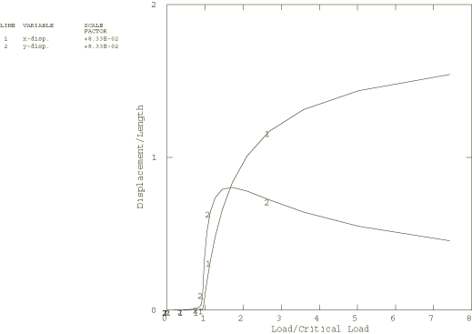
A cantilever beam is considered for the Euler buckling problem. All degrees of freedom are restrained at the clamped end of the beam. The input data are shown in beambuckle_b31os_isec_flex.inp. An interesting extension of this buckling problem is to examine the response of the column far into the postbuckling range. This is the simplest of the classical “elastica” problems, an elastica being an elastic curve bent by some load (see Timoshenko and Gere, 1961). For this study an initial imperfection in the shape of the lowest buckling mode, with a peak magnitude of 10% of the beam thickness, is introduced. The Riks technique is used. An axial force, equal in magnitude to the critical load, is applied, and the analysis is stopped when the axial force becomes six times the applied load.
All components of displacement, and the rotation about the x-axis, are restrained at one of the support nodes for the lateral/torsional buckling problems. Displacements in the y- and z-directions, and rotation about the x-axis, are restrained at the other support node. Beam sections are tested using an I-section and an arbitrary section type. General beam sections are tested using an I-section, an arbitrary section, and a general section type. (A general beam section with linear response in combination with the open section beam elements requires that the warping constants be specified.)
beambuckle_b31os_isec_lat.inp shows the input data used for the eigenvalue buckling analysis. The distributed load is applied as load type PZ, with a magnitude of 1 N/m. A load-displacement analysis is then performed, with collapse being defined by large motion occurring under very small load increments. The model used must provide for switching to the buckling mode. A slight initial imperfection is used for this purpose. The first mode from the eigenvalue buckling analysis is scaled to have a maximum rotation equal to 1% of the flange width. The translational displacements are equally scaled and added to the nodal coordinates to define the perturbed or imperfect geometric data. The normal at each node is defined based upon the scaled rotations from the eigenvalue analysis. Since instabilities are expected, the Riks method is used. The analysis is terminated when the lateral displacement () of the middle node is greater than the flange width of the beam. The input for this load-displacement analysis is shown in beambuckle_b31os_arbsec_lat.inp.
The model used for the eigenvalue torsional buckling analysis is the same as that used for the lateral buckling analysis. Here, a concentrated axial load of 10 N is applied to one end of the beam. beambuckle_b31os_tors_gsec.inp shows the input used for this analysis.
![]()
Results and discussion
The critical flexural buckling load for mode n, as given by Timoshenko and Gere (1961), is
where E is Young's modulus, I is the moment of inertia, and l is the length of the beam.
The buckling load estimates provided by Abaqus are shown in Table 1. For practical purposes only the lowest mode is of significance, and a coarser mesh than used here would give that mode accurately.
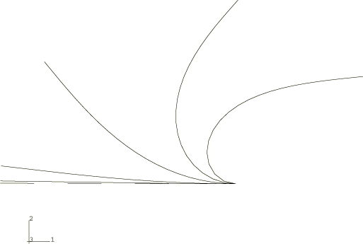
For the elastica problem, the x and y positions of the tip of the column are shown as functions of the load in Figure 2. The deformed shape of the column is plotted in Figure 3.
The critical lateral buckling load is given by Timoshenko and Gere (1961) as
where E is Young's modulus, G is the shear modulus, l is the length of the beam, and is a dimensionless factor dependent upon the loading and on the ratio , where is the warping constant
and J is the torsion constant
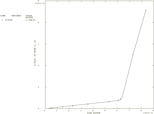
Here is the thickness of the flange, is the thickness of the web, h is the height of the cross-section, and b is the width of the flange. For our model, this gives a critical load of 62.5 N/mm. The eigenvalue buckling analysis with 20 linear open section beam elements predicts a critical load of 62.47 N/mm. The load-displacement analysis shows a severe loss of stiffness at a load very close to the expected critical value, as shown in Figure 4.
The critical torsional buckling load for mode n is given by Timoshenko and Gere (1961) as
where A is the cross-sectional area and is the polar moment of inertia of the cross-section about the shear center. The torsional buckling load estimates provided by Abaqus are shown in Table 2.
![]()
Input files
- beambuckle_b31os_isec_flex.inp
-
Element B31OS with BEAM SECTION, SECTION=I for the flexural eigenvalue buckling prediction.
- beambuckle_b31os_isec_lat.inp
-
Element B31OS with BEAM SECTION, SECTION=I for the lateral eigenvalue buckling analysis.
Using the Lanczos solver
- beambuckle_b31os_lanczos.inp
-
Same as beambuckle_b31os_isec_flex.inp, except that it uses FREQUENCY, EIGENSOLVER=LANCZOS for the eigenvalue buckling analysis in the given ranges.
Lateral buckling load-displacement analysis
- beambuckle_b31os_load_isec.inp
-
Element B31OS with BEAM SECTION, SECTION=I.
- beambuckle_b31os_dload_isec.inp
-
Element B31OS with BEAM SECTION, SECTION=I and pressure load.
- beambuckle_b31os_arbsec_lat.inp
-
Element B31OS with BEAM SECTION,SECTION=ARBITRARY.
- beambuckle_b31os_load_gseci.inp
-
Element B31OS with BEAM GENERAL SECTION, SECTION=I.
- beambuckle_b31os_load_arbsec.inp
-
Element B31OS with BEAM GENERAL SECTION, SECTION=ARBITRARY.
- beambuckle_b31os_load_gsecg.inp
-
Element B31OS with BEAM GENERAL SECTION, SECTION=GENERAL.
- beambuckle_b32os_load_isec.inp
-
Element B32OS with BEAM SECTION, SECTION=I.
- beambuckle_b32os_load_arbsec.inp
-
Element B32OS with BEAM SECTION,SECTION=ARBITRARY.
- beambuckle_b32os_load_gseci.inp
-
Element B32OS with BEAM GENERAL SECTION, SECTION=I.
- beambuckle_b32os_load_garbsec.inp
-
Element B32OS with BEAM GENERAL SECTION, SECTION=ARBITRARY.
- beambuckle_b32os_load_gsecg.inp
-
Element B32OS with BEAM GENERAL SECTION, SECTION=GENERAL.
Torsional eigenvalue buckling analysis
- beambuckle_b31os_tors_isec.inp
-
Element B31OS with BEAM SECTION, SECTION=I.
- beambuckle_b31os_tors_gsec.inp
-
Element B31OS with BEAM GENERAL SECTION.
- beambuckle_b31os_tors_gseci.inp
-
Element B31OS with BEAM GENERAL SECTION, SECTION=I.
- beambuckle_b32os_tors_isec.inp
-
Element B32OS with BEAM SECTION, SECTION=I.
Elastica study
- beambuckle_b21_elastica.inp
-
Element B21 with BEAM GENERAL SECTION, SECTION=GENERAL.
- beambuckle_b21h_elastica.inp
-
Element B21H with BEAM GENERAL SECTION, SECTION=GENERAL.
- beambuckle_b22_elastica.inp
-
Element B22 with BEAM GENERAL SECTION, SECTION=GENERAL.
- beambuckle_b22h_elastica.inp
-
Element B22H with BEAM GENERAL SECTION, SECTION=GENERAL.
- beambuckle_b23_elastica.inp
-
Element B23 with BEAM GENERAL SECTION, SECTION=GENERAL.
- beambuckle_b23h_elastica.inp
-
Element B23H with BEAM GENERAL SECTION, SECTION=GENERAL.
- beambuckle_b31_elastica.inp
-
Element B31 with BEAM SECTION, SECTION=I.
- beambuckle_b31h_elastica.inp
-
Element B31H with BEAM SECTION, SECTION=I.
- beambuckle_b31os_elastica.inp
-
Element B31OS with BEAM SECTION, SECTION=I.
- beambuckle_b31osh_elastica.inp
-
Element B31OSH with BEAM SECTION,SECTION=I.
- beambuckle_b32_elastica.inp
-
Element B32 with BEAM SECTION, SECTION=I.
- beambuckle_b32h_elastica.inp
-
Element B32H with BEAM SECTION, SECTION=I.
- beambuckle_b32os_elastica.inp
-
Element B32OS with BEAM SECTION, SECTION=I.
- beambuckle_b32osh_elastica.inp
-
Element B32OSH with BEAM SECTION,SECTION=I.
- beambuckle_b33_elastica.inp
-
Element B33 with BEAM SECTION, SECTION=I.
- beambuckle_b33h_elastica.inp
-
Element B33H with BEAM SECTION, SECTION=I.
- beambuckle_pipe21_elastica.inp
-
Element PIPE21 with BEAM SECTION,SECTION=PIPE.
- beambuckle_pipe21h_elastica.inp
-
Element PIPE21H with BEAM SECTION,SECTION=PIPE.
- beambuckle_pipe22_elastica.inp
-
Element PIPE22 with BEAM SECTION,SECTION=PIPE.
- beambuckle_pipe22h_elastica.inp
-
Element PIPE22H with BEAM SECTION,SECTION=PIPE.
- beambuckle_pipe31_elastica.inp
-
Element PIPE31 with BEAM SECTION,SECTION=PIPE.
- beambuckle_pipe31h_elastica.inp
-
Element PIPE31H with BEAM SECTION,SECTION=PIPE.
- beambuckle_pipe32_elastica.inp
-
Element PIPE32 with BEAM SECTION,SECTION=PIPE.
- beambuckle_pipe32h_elastica.inp
-
Element PIPE32H with BEAM SECTION,SECTION=PIPE.
![]()
References
- Theory of Elastic Stability, 2nd Edition, McGraw-Hill, New York, 1961.
![]()
Tables
| Eigenvector | Estimated | Theoretical | Direction |
|---|---|---|---|
| buckling load | buckling load | ||
| 1 | 0.4371 | 0.4398 | y (1) |
| 2 | 3.9267 | 3.9587 | y (2) |
| 3 | 7.4575 | 7.5182 | z (1) |
| 4 | 10.8670 | 10.9965 | y (3) |
| 5 | 21.1796 | 21.5530 | y (4) |
| 6 | 34.7394 | 35.6285 | y (5) |
| 7 | 51.3717 | 53.2228 | y (6) |
| 8 | 63.0448 | 67.6640 | z (2) |
| 9 | 70.8435 | 74.3360 | y (7) |
| 10 | 92.8553 | 98.9680 | y (8) |
| number of half sine waves | |||
| Eigenvector | Estimated | Theoretical | Mode (n) |
|---|---|---|---|
| buckling load | buckling load | ||
| 1 | 1.7544 | 1.7704 | Flexural - y (1) |
| 2 | 6.4235 | 6.4134 | Torsional (1) |
| 3 | 7.0577 | 7.0814 | Flexural - y (2) |
| 4 | 13.1363 | 13.0300 | Torsional (2) |
| 5 | 16.0307 | 15.9330 | Flexural - y (3) |
| 6 | 24.5735 | 24.0590 | Torsional (3) |
| 7 | 28.8769 | 28.3260 | Flexural - y (4) |
| 8 | 29.7522 | 30.1110 | Flexural - z (1) |
| 9 | 41.1234 | 39.4980 | Torsional (4) |
| 10 | 45.8840 | 44.2590 | Flexural - y (5) |
![]()
Figures