Anisotropic hyperelastic modeling of arterial layers | ||
| ||
ProductsAbaqus/StandardAbaqus/Explicit
Problem description
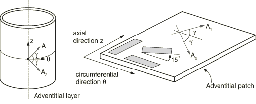
We consider the numerical analysis of simple tensile tests of adventitial strips cut along the axial and circumferential directions of the artery, as well as a strip cut at an angle of 15° with respect to the circumferential direction, as illustrated in Figure 1. Following the work of Gasser, Holzapfel, and Ogden (2006), the adventitial strips considered in the study have referential dimensions of 10.0 mm length × 3.0 mm width × 0.5 mm thickness and are assumed to be stress free in the reference configuration. It is assumed that two families of collagen fibers are embedded in the specimens, symmetrically arranged with respect to the axial and circumferential directions of the artery and with no component in the radial (thickness) direction, as shown in Figure 1. The angle between the mean orientation of the fibers and the circumferential direction is =49.98°. The specimens are loaded in the longitudinal direction, and their end faces are not allowed to deform. Using appropriate symmetry boundary conditions, only one-eighth of the geometry is modeled in the case of strips cut along the axial and circumferential directions. A full scale simulation is carried out for strips cut at a 15° angle with respect to the circumferential direction. The finite element model of the specimens consists of a 20 × 10 × 2 mesh for the simulations considering one-eighth symmetry and a 40 × 20 × 4 mesh for the full scale simulations.
The numerical analyses are conducted using the static analysis procedure in Abaqus/Standard. Linear solid hybrid elements (C3D8H) are used to model the incompressible deformation of the arterial layers. For comparison, the solution is also computed in Abaqus/Explicit assuming quasi-static loading conditions. Since Abaqus/Explicit has no mechanism for imposing the incompressibility constraint, some amount of compressibility is introduced in the material response in the Abaqus/Explicit simulations and linear solid elements (C3D8R) are used.
Material
The mechanical response of the adventitial layer is modeled using the anisotropic hyperelastic strain energy function proposed by Gasser, Holzapfel, and Ogden (2006) to model arterial layers with distributed collagen fiber orientations. Details of the model are given in Holzapfel-Gasser-Ogden form and Holzapfel-Gasser-Ogden form.
It is assumed that the arterial layer is composed of two families of collagen fibers embedded in a soft incompressible ground matrix. The families of fibers have mean orientations characterized by the vectors and in the reference configuration, but the orientations of the fibers within each family are dispersed. The model incorporates a scalar structure parameter, (), that characterizes the level of dispersion of the collagen orientations. When =0, the fibers are perfectly aligned (no dispersion). When =1/3, the fibers are randomly distributed and the material becomes isotropic. A value of =0.226 is used in the numerical simulations. For comparison, numerical tests are also carried out assuming ideal alignment of the collagen fibers (=0).
The material properties are taken from Gasser, Holzapfel, and Ogden (2006) and are shown in Table 1. They are based on least-squares fitting of longitudinal and circumferential tension tests of adventitial strips of nine iliac arteries carried out by Holzapfel, Sommer, and Regitnig (2004).
![]()
Loading and controls
The mounting of the specimen in the testing machine is modeled by constraining both ends of the strip. The strips are loaded in the tensile direction, and their end faces are not allowed to deform.
In the Abaqus/Standard simulations the static procedure is used with a prescribed load of 2.0 N. Geometric nonlinearities are considered in this step to account for the large deformations of the adventitial strip.
Since Abaqus/Explicit is a dynamic analysis program and we are interested in a static solution to the problem, care must be taken to avoid significant inertia effects as the adventitial strip is loaded. A smooth step amplitude curve is used to prescribe the uniaxial displacement of the strip and to promote a quasi-static solution in the Abaqus/Explicit simulations. The simulations are run in double precision.
![]()
Results and discussion
Results for the Abaqus/Standard and Abaqus/Explicit analyses are discussed in the following sections.
Abaqus/Standard results
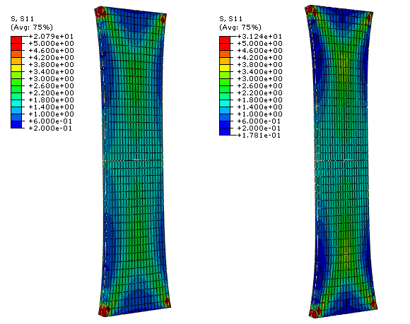
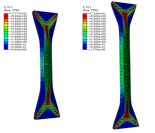
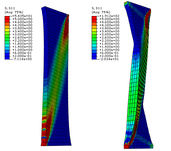
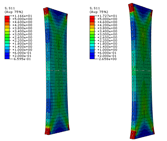
Figure 2 shows the computed stress in the tensile direction for the axial (left) and circumferential (right) specimens with distributed fibers (=0.226) for a tensile load of 2.0 N. The thickness of the specimens remains approximately constant during loading, with small transition zones at the ends of the strips. The corresponding results for the case of perfectly aligned fibers (=0) are shown in Figure 3. In this case the embedded collagen fibers need to rotate significantly toward the loading direction before they can carry significant load. The combined effect of the large rotation of the fibers and the incompressibility constraint causes the thickness of the specimen to increase (and the width to decrease) in the middle region of the strip, away from the restrained boundaries. The transition areas at the end of the strip resemble deformation patterns similar to those observed in woven fabrics.
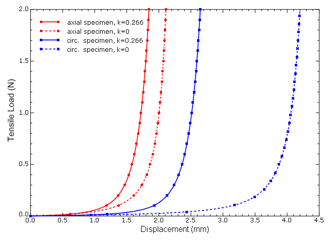
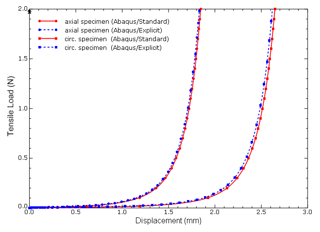
Figure 4 shows the computed load versus displacement curves for the circumferential and axial specimens. The dashed curves correspond to the simulations with ideally aligned fibers, and the continuous curves correspond to the simulations that include dispersion. As seen in the figure, the material response is very soft at low stretches; only a small force is needed to achieve significant extension. Once the collagen fibers are approximately aligned with the loading direction, the material stiffens rapidly. This is particularly evident in the case of the circumferential specimen with =0; the alignment requires very large average stretches, and the specimen stiffens at a displacement of about 4 mm. In contrast, when dispersion is included in the simulation, the collagen fibers need to rotate less before they carry load compared with the ideally aligned case. Therefore, the dispersion of the collagen fibers leads to a stiffer macroscopic response of the specimens. Specifically, the dispersion parameter controls the elongation at which the specimen stiffens.
These numerical results for axial and circumferential specimens are in agreement with the results reported in Gasser, Holzapfel, and Ogden (2006).
Figure 5 shows the stress in the loading direction in a specimen cut at an angle of 15° with respect to the circumferential direction. The plot on the left corresponds to the case of distributed fibers, and the plot on the right corresponds to the case of ideally aligned fibers. Again, we observe that significantly more rotation is required for ideally aligned fibers before they carry load.
Abaqus/Explicit results
For comparison, the axial and circumferential specimens with distributed fibers are also analyzed using Abaqus/Explicit. Figure 6 shows the stress in the tensile direction for the axial (left) and circumferential (right) specimens at the end of the Abaqus/Explicit simulations. As illustrated in Figure 7, the load-displacement response computed in Abaqus/Explicit compares well with that obtained in Abaqus/Standard. Small discrepancies in the results can be attributed to the use of different element types as well as minor dynamic effects and some amount of material compressibility in the Abaqus/Explicit simulations.
![]()
Input files
Abaqus/Standard input files
- adventitia_axial.inp
Simple tension of adventitial strip cut along axial direction; distributed fibers (=0.226); 1/8 symmetry model; C3D8H elements.
- adventitia_axial_k0.inp
Simple tension of adventitial strip cut along axial direction; ideally aligned fibers (=0); 1/8 symmetry model; C3D8H elements.
- adventitia_circ.inp
Simple tension of adventitial strip cut along circumferential direction; distributed fibers (=0.226); 1/8 symmetry model; C3D8H elements.
- adventitia_circ_k0.inp
Simple tension of adventitial strip cut along circumferential direction; ideally aligned fibers (=0); 1/8 symmetry model; C3D8H elements.
- adventitia_15deg.inp
Simple tension of adventitial strip cut at an angle of 15° with respect to the circumferential direction; distributed fibers (=0.226); C3D8H elements.
- adventitia_15deg_k0.inp
Simple tension of adventitial strip cut at an angle of 15° with respect to the circumferential direction; ideally aligned fibers (=0); C3D8H elements.
Abaqus/Explicit input files
- adventitia_axial_xpl.inp
Simple tension of adventitial strip cut along axial direction; distributed fibers (=0.226); 1/8 symmetry model; compressible; C3D8R elements.
- adventitia_circ_xpl.inp
Simple tension of adventitial strip cut along circumferential direction; distributed fibers (=0.226); 1/8 symmetry model; compressible; C3D8R elements.
Additional Abaqus/Standard input files not used for discussion
- adventitia_axial_cps4r.inp
Simple tension of adventitial strip cut along axial direction; distributed fibers (=0.226); plane stress 1/4 symmetry model; incompressible; CPS4R elements.
- adventitia_axial_m3d4r.inp
Simple tension of adventitial strip cut along axial direction; distributed fibers (=0.226); plane stress 1/4 symmetry model; incompressible; M3D4R elements.
- adventitia_axial_s4r.inp
Simple tension of adventitial strip cut along axial direction; distributed fibers (=0.226); plane stress 1/4 symmetry model; incompressible; S4R elements.
Additional Abaqus/Explicit input files not used for discussion
- adventitia_axial_m3d4_xpl.inp
Simple tension of adventitial strip cut along axial direction; distributed fibers (=0.226); plane stress 1/4 symmetry model; incompressible; M3D4 elements.
- adventitia_axial_k0_m3d4_xpl.inp
Simple tension of adventitial strip cut along axial direction; ideally aligned fibers (=0); plane stress 1/4 symmetry model; incompressible; M3D4 elements.
- adventitia_circ_m3d4_xpl.inp
Simple tension of adventitial strip cut along circumferential direction; distributed fibers (=0.226); plane stress 1/4 symmetry model; incompressible; M3D4 elements.
- adventitia_circ_k0_m3d4_xpl.inp
Simple tension of adventitial strip cut along circumferential direction; ideally aligned fibers (=0); plane stress 1/4 symmetry model; incompressible; M3D4 elements.
- adventitia_15deg_m3d4_xpl.inp
Simple tension of adventitial strip cut at an angle of 15° with respect to the circumferential direction; distributed fibers (=0.226); plane stress 1/4 symmetry model; incompressible; M3D4 elements.
- adventitia_15deg_k0_m3d4_xpl.inp
Simple tension of adventitial strip cut at an angle of 15° with respect to the circumferential direction; ideally aligned fibers (=0); plane stress 1/4 symmetry model; incompressible; M3D4 elements.
![]()
References
- “Hyperelastic Modelling of Arterial Layers with Distributed Collagen Fibre Orientations,” Journal of the Royal Society Interface, vol. 3, pp. 15–35, 2006.
- “A New Constitutive Framework for Arterial Wall Mechanics and a Comparative Study of Material Models,” Journal of Elasticity, vol. 61, pp. 1–48, 2000.
- “Anisotropic Mechanical Properties of Tissue Components in Human Atherosclerotic Plaques,” Journal of Biomechanical Engineering, vol. 126, pp. 657–665, 2004.
![]()
Tables
| Holzapfel-Gasser-Ogden energy function coefficients: | |
| = 3.82 kPa | |
| = 996.6 kPa | |
| = 524.6 | |
| = 0.226 | |
| = 0 ( = 1× 10⁻⁶ for compressible case) | |
| Fiber directions (for strips cut along circumferential direction): | |
| with = 49.98°. | |
![]()
Figures