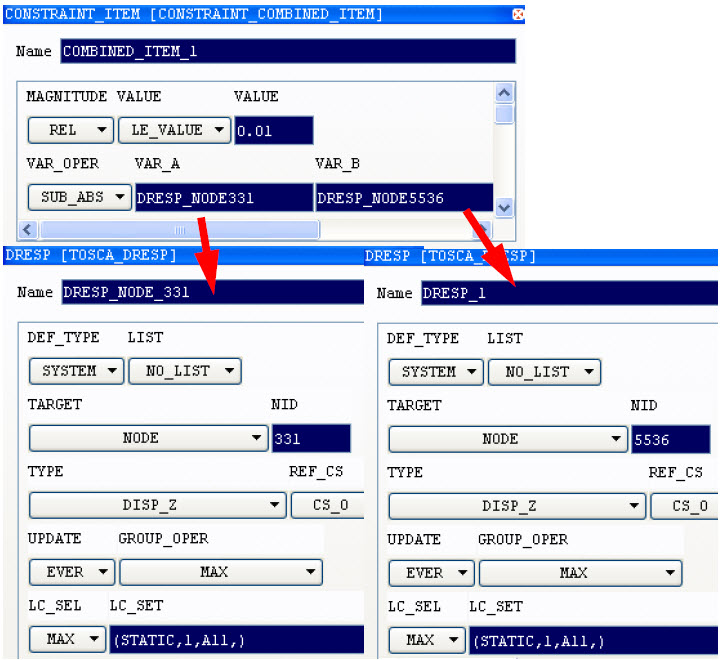
Define the Displacement Constraint in Tosca ANSA® environment
In CONSTRAINT_ITEM dialog, create a COMBINED_ITEM design response with
VAR_OPER = SUB_ABS.
To create the individual design response for each of the two displacements, press "?" key in the VARIABLE_1 field. Press New in the appeared dialog, then
choose TOSCA_DRESP.
In the DRESP dialog, choose TARGET = NODE and TYPE = DISP_Z (in
case of the displacement in z-direction). Enter the node ID in the NID
field and the load case(s)
in the LC_SET field. Double click
on the name of the design response in TOSCA HELP window
so that this design response is entered in VARIABLE_1
field of the COMBINED_ITEM design response. Repeat the steps
for the second displacement entered in VARIABLE_2
field.

Define a Displacement Constraint in Tosca Structure.gui
Define a design response (DRESP) for the displacement of the first node. For a list of existing types, see Overview of Displacement and Rotation. Note:
The total absolute
value cannot be used as design response.
Define a design response for the displacement of the second node,
similar to the first one. To define a design response with the difference of the nodal displacement
from the two nodes, choose . In the DRESP dialog, select
DefType = Operator and Operator = SUB_ABS.
Define a Displacement Constraint in Tosca Extension for ANSYS® Workbench
- Differences between displacements (OPER) are not available yet.
Common Steps for Tosca ANSA® environment
and Tosca Structure.gui
Define a second constraint for the relative material volume. Only a few elements will be removed in the short arm in order to obtain
equal displacements of the two arms. In most cases the intention is to
have a structure with a given weight and the maximum stiffness. Define the objective function as minimization of the compliance
of the whole model. This is defined as the sum of the strain energy of
all elements (ALL_ELEMENTS element group).
SIMULIA Tosca Structure Parameter File
- The commands in the parameter file for this problem look like follows:
DRESP
 ID_NAME        = DISP_TIP_RIGHT
 TYPE           = DISP_Z
 DEF_TYPE       = SYSTEM
 LC_SET         = STATIC,1,
 GROUP_OPER     = Max
 ND_GROUP       = TIP_RIGHT
END_

DRESP
 ID_NAME        = DISP_TIP_LEFT
 TYPE           = DISP_Z
 DEF_TYPE       = SYSTEM
 LC_SET         = STATIC,1,
 GROUP_OPER     = Max
 ND_GROUP       = TIP_LEFT
END_
DRESP
 ID_NAME        = DISP_DIFFERENCE
 DEF_TYPE       = OPER
 VAR_OPER       = SUB_ABS
 VAR_A          = DISP_TIP_RIGHT
 VAR_B          = DISP_TIP_LEFT
END_

DRESP
 ID_NAME        = DRESP_SUM_ENERGY_LC1
 TYPE           = STRAIN_ENERGY
 DEF_TYPE       = SYSTEM
 LC_SET         = STATIC,1
 GROUP_OPER     = SUM
 EL_GROUP       = ALL_ELEMENTS
END_

OBJ_FUNC
 ID_NAME        = MY_OBJ_FUNC
 TARGET         = MIN
 DRESP          = DRESP_SUM_ENERGY_LC1
END_

CONSTRAINT
 ID_NAME        = DISP_DIFF_CONSTRAINT
 MAGNITUDE      = ABS
 DRESP          = DISP_DIFFERENCE
 LE_VALUE       = 0.1
END_

DRESP
 ID_NAME        = DRESP_VOL_TOPO
 TYPE           = VOLUME
 DEF_TYPE       = SYSTEM
 GROUP_OPER     = SUM
 EL_GROUP       = ALL_ELEMENTS
END_

CONSTRAINT
 ID_NAME        = VOL_CONSTRAINT
 MAGNITUDE      = REL
 DRESP          = DRESP_VOL_TOPO
 LE_VALUE       = 0.3
END_
|