Maximizing the Band Gap | ||
| ||
Context:
In the following optimization definition, the structure should be designed so that the first four eigenfrequencies are as far away as possible from 150 Hz in order to avoid the resonance at this frequency.
This is done by defining the first four eigenfrequencies as single design responses with TYPE = DYN_FREQ and applying the eigenfrequencies in the objective function using a min-max-formulation as follows:
DRESP
 ID_NAME = eigenfrequency_1
 DEF_TYPE = SYSTEM
 TYPE = DYN_FREQ
 LC_SET = MODAL, ALL, 1
END_

DRESP
 ID_NAME = eigenfrequency_2
 DEF_TYPE = SYSTEM
 TYPE = DYN_FREQ
 LC_SET = MODAL, ALL, 2
END_

DRESP
 ID_NAME = eigenfrequency_3
 DEF_TYPE = SYSTEM
 TYPE = DYN_FREQ
 LC_SET = MODAL, ALL, 3
END_

DRESP
 ID_NAME = eigenfrequency_4
 DEF_TYPE = SYSTEM
 TYPE = DYN_FREQ
 LC_SET = MODAL, ALL, 4
END_

OBJ_FUNC
 DRESP = eigenfrequency_1, 1.0, 150.0
 DRESP = eigenfrequency_2, 1.0, 150.0
 DRESP = eigenfrequency_3, 1.0, 150.0
 DRESP = eigenfrequency_4, 1.0, 150.0
 TARGET = MINMAX
END_
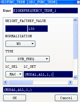
Define an Objective Function for a Band Gap Maximization in Tosca ANSA® environment
For a band gap maximization with four eigenfrequencies there are four Design Responses needed, one for every eigenfrequency.
Set the reference value (REF_VALUE = 150) for each objective function term as shown in the following figure.
The only difference between the terms is the mode number represented by the third parameter in LC_SET field (1 for the first design response, 2 for the second one, etc.).
![]()
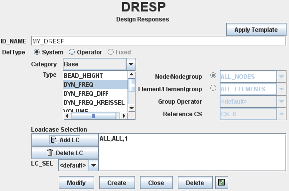
Define an Objective Function for a Band Gap Maximization in Tosca Structure.gui
Choose the load cases by pressing Add LC button and setting Analysis Type to MODAL, entering the load case ID and the numbers of eigenmodes (1 for first term, 2 for the second one, etc.) in Eigenmode/Subcase field.
![]()
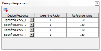
Define an Objective Function for a Band Gap Maximization in Tosca Extension for ANSYS® Workbench
In the Design Responses dialog, set the Reference Value (to 150 e.g.) for each listed Design Response as shown in the following figure: