Overview of Stress in Topology Optimization | ||
| ||
The is the elemental centroidal von Mises stress, is the reference stress and is a factor for interpolating the stresses of the elements having intermediate densities (given by the topology optimization, see Stress Interpolation ).
Only von Mises stress can be applied in topology optimization.
Analysis Types: Static Linear and Non-Linear (Contact) Analysis
Geometrical and material nonlinearities in element group are not supported.
For weighted centroidal von Mises stress for topology optimization the following table shows the allowed combinations between strategy and the items OBJ_FUNC and CONSTRAINT with C for controller and S for sensitivity based optimization.
TOPO |
SHAPE |
BEAD |
SIZING |
|
|---|---|---|---|---|
OBJ_FUNC |
S |
|||
CONSTRAINT |
S |
Note:
Stress applied in topology optimization cannot directly be compared to the von Mises stress given as output from the finite element solver. Only for solid elements ( ) the von Mises stresses given by Tosca Structure stresses is equal to the von Mises stresses as output from the FE-solver (see Stress Interpolation).
![]()
Stress Calculation
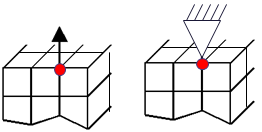
The von Mises stress is calculated in the elemental centroid for avoiding stress singularities which might be present in the initial model or appear in the non-smoothed topology optimized structures. This is also shown in the following figure:
 |
![]()
Reference Stress for Objective Function
The reference stress is defined in the objective function command or will be automatically calculated by SIMULIA Tosca Structure for the objective function.
A reference stress for the objective function terms can be directly defined as
OBJ_FUNC
  ID_NAME    = OBJ_FUNCTION_ID
  DRESP    = DRESP_ID_1,<weight_fact_1>, <ref_stress_1>
  DRESP    = DRESP_ID_2,<weight_fact_2>, <ref_stress_2>
  ...........
  TARGET = MIN
END_
where <reference stress 1> and <reference stress 2> correspond to . The reference stress values should not be chosen too low as this might cause numerical singularities. This corresponds to
If the user does not define a reference stress in the objective function command then SIMULIA Tosca Structure automatically determines a reference stress, which is generated in the initial optimization iteration and is written to TOSCA.OUT.
![]()
Constraint Value
A limitation on the stresses can be formed for a DRESP of type SIG_TOPO_MISES used in a constraint definition with the LE_VALUE parameter:
CONSTRAINT
  ID_NAME   = STRESS_CONSTRAINT
  DRESP     = DRESP_STRESS_ID
  MAGNITUDE = ABS
  LE_VALUE  = <stress_constraint>
END_
This corresponds to restricting the weighted centroidal von Mises stress by the constraint value stress_constraint=:
Important:
|
![]()
Stress Interpolation
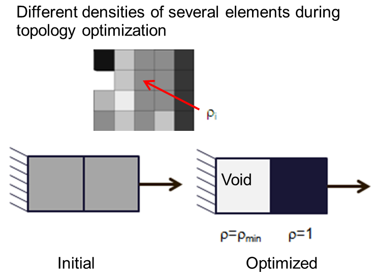
The factor describes a function for the interpolation of stresses depending of the density of the element i.
The interpolation is needed because during the topology optimization the densities of the elements are modified and can have a minimum value close to zero. Stress values calculated by the solver for transition or soft elements (i.e. elements with low density) have no real physical meaning for the stresses and must be weighted by a factor to allow for a successful optimization convergence.
The following figure shows the densities of elements during the optimization: On the left the initial equal density of all elements can be seen, at the top there are the modified densities during the topology optimization iterations and on the right the final density values for the optimized model.
 |
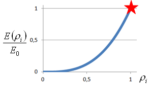
The stress interpolation for intermediate densities is similar to the stiffness material interpolation and can be illustrated as
 |
Thus, the stress measure SIG_TOPO_MISES applied in topology optimization cannot be directly compared to the von Mises stresses seen as output from the finite element solver. Only for solid elements () and with an active stress constraint the SIG_TOPO_MISES corresponds to the von Mises stresses calculated by the FE-solver.
Solid elements: |
|
Von Mises stress = constraint stress: |
![]()
Element Group
The element group for the stress measure can consist of both design and non-design elements.
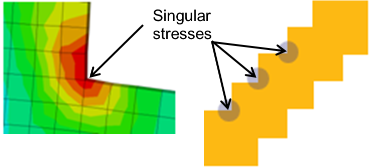
Frequently, the initial model for the optimization contains non-physical modeling around loaded nodes and boundary conditions, respectively. The user should avoid including stresses from stress singularities caused by external loaded nodes or by boundary conditions, as shown in the following figure. These singularities are eliminated by excluding these elements from the group used for calculating the DRESP.
 |
![]()
Supported Element Types
Supported element types are 3D standard continuum elements:
- Hexahedral 8 and 20 node elements
- Tetrahedral 4 (not recommended!) and 10 node elements
- Pentahedron 6 and 15 nodes elements
All linear isotropic materials are supported for the elements in the element group. Anisotropic and non-linear materials both inside and outside the design domain (DV_TOPO) are only supported if the stresses of these materials are not a part of the element group applied for calculation of the DRESP of TYPE = SIG_TOPO_MISES.
Note: Pyramidal 5 and 13 node elements as well as shell elements are not supported.
| Important: Shear and volume locking in the finite element yield wrong results not only in the finite element analysis but can also cause optimization convergence problems when such stress responses are included in the optimization formulation. Especially, the linear 4 node tetrahedral elements should be avoided. Instead it is recommended to use the quadratic10 node tetrahedral element or the linear 8 node hexahedral element. |
![]()
Load Cases
Several load cases can be defined for the stress measure.
Static linear analysis is supported. For static non-linear analysis only contact is supported.
Thus, geometrical nonlinearities (like large deformation) and non-linear materials are not supported.