Settings for Tosca Structure.shape | ||
| ||
Treatment of the midside nodes (MID_NODES)
Only corner nodes (from finite elements) are supported as design nodes. Mid-side nodes may be included in the design node group but the optimization displacements of the midside nodes of second order elements is interpolated from the optimization displacement of the adjacent corner nodes.
The interpolation method can be chosen with the MID_NODES parameter:
									...
          MID_NODES = [ LINEAR | INTERPOLATE ]
         ...
- With the default option LINEAR the midside node positions are linearly interpolated from the optimized position of the connected corner nodes.
- With the option INTERPOLATE the midside node optimization displacements are interpolated from the optimization displacement of the connected corner nodes.
Note:
If in the initial position the midside node is on the line between the corner nodes there will be no difference between the two methods. But if the edge of the element is bent only with INTERPOLATE the bending can be prevented.
![]()
Updating the optimization displacement vectors (VECTOR)
An optimization displacement vector is determined by the optimization algorithm for every design node. This vector graphically corresponds to the outer surface unit normal at the node and indicates the optimization displacement direction. Restrictions influencing the direction (DVCON_SHAPE with CHECK_DOF and CHECK_BC) are included in the calculation of the optimization displacement vectors.
The VECTOR parameter enables the user to specify the design cycle in which to determine the optimization displacement vectors:
									...
          VECTOR = [ EVER | FIRST ]
         ...
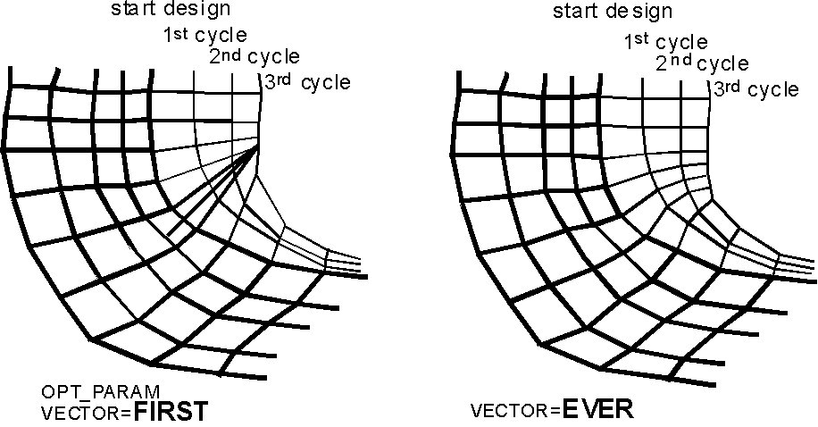
- The default setting is VECTOR=EVER. The optimization displacement vectors are re-determined in every design cycle by the optimization algorithm and consequently adjusted to changed conditions (for example shape of the structure, effective restrictions, mesh quality, etc.).
- With the setting VECTOR=FIRST, the optimization displacement vectors are calculated only once in the first design cycle and then kept constant in all other cycles. The optimization displacement vectors are not adjusted to changes in conditions during the remaining part of the optimization.
The following figure provides an illustration of the two settings. Generally, VECTOR=EVER provides better results since the mesh smoothing algorithm is less restricted and a better mesh can be achieved. However, in certain cases the setting VECTOR=FIRST can be of advantage.
 |