General Information | |||||||
|
| ||||||
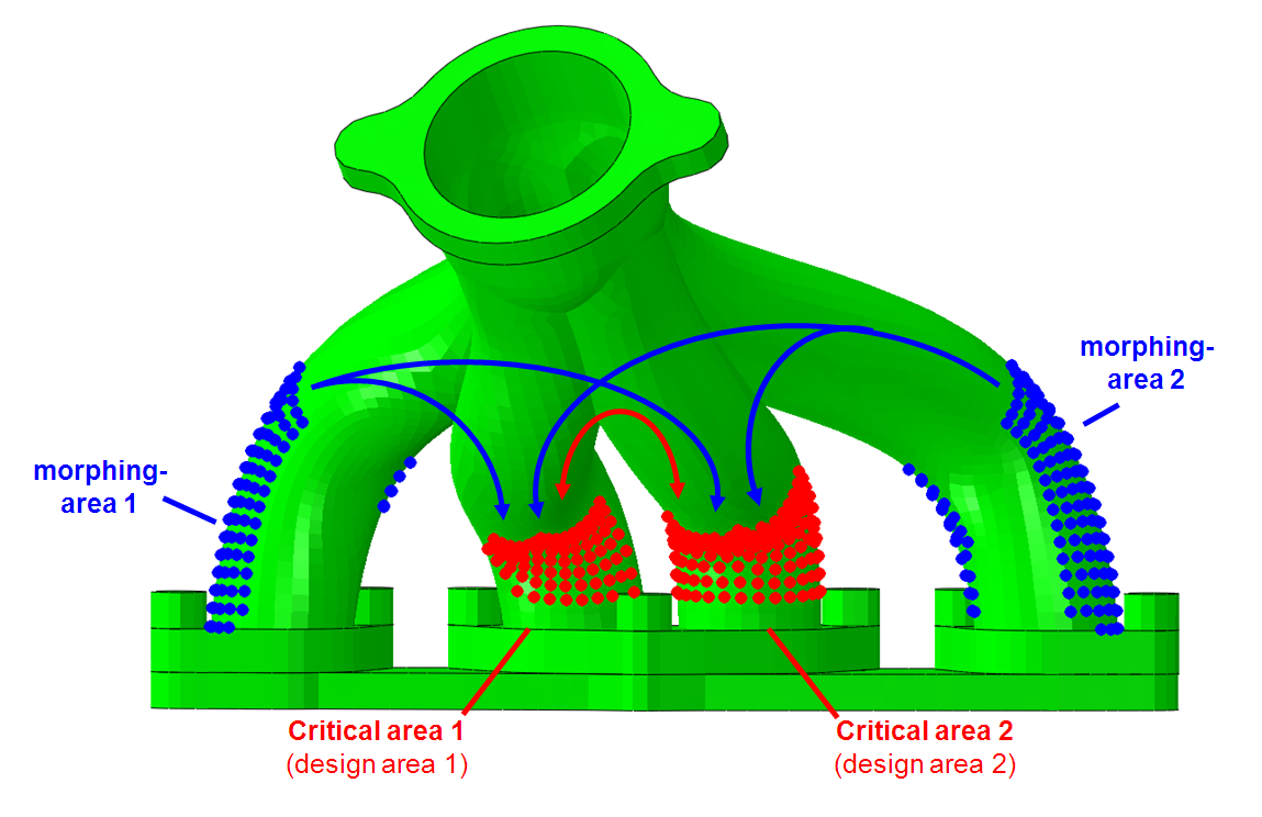
Shape optimization results can thus be improved through start with a design where these global effects are already considered.
 |
Using Tosca Structure.morph several design variants can be created automatically. With these variants global interactions and influences can be assessed and evaluated prior to a local shape optimization. Thereby a specific design of experiments is performed which modifies the predefined morph areas according to an user defined experiment plan.
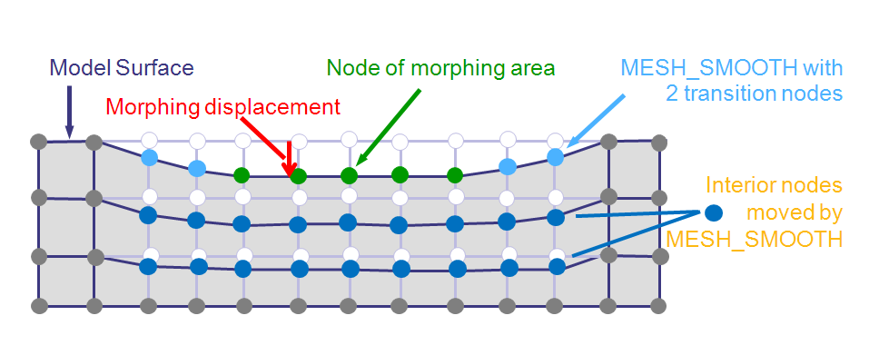
Morphing is offered as add-on to shape optimization, where "morphed models" are created based on the experiment plan. In each step of the morphing process (each experiment) a constant displacement is applied independently to the nodes of each morph area. The modified (morphed) model is analysed and the requested design responses (i.e. all values required for the optimization task) are evaluated.
The base of the parameter file is a shape optimization task where all nodes in any MORPH_AREA must be part of the design area. MESH_SMOOTH and DVCON_SHAPE commands defined in OPTIMIZE are referenced by MORPH -command and thus used. Objective function and eventually constraint define relevant values for post-processing and evaluation of the quality of the design. These values will be available e.g. as fringe plots on the several morphing variants.
Morphing displacement
For each step of the morphing process a constant displacement is applied independently to the nodes of each morph area.
 |
The displacements are defined in an external morphing parameter file <morph_csv_file_name>.csv referenced in the MORPH command. The external file offers easier access from external process automation programs (like ISight or OPTIMUS) and reusabiltiy:
![]()
Morphing parameter file
0, <morph_def_name_1>, <morph_def_name_2>,<morph_..._3>, …
!
1, < morph_disp _1>, < morph_disp _2>, < morph_disp _3>, …
2, < morph_disp _1>, < morph_disp _2>, < morph_disp _3>, …
3, < morph_disp _1>, < morph_disp _2>, < morph_disp _3>, …
4, < morph_disp _1>, < morph_disp _2>, < morph_disp _3>, …
5, …
The first line in the morphing parameter file contains the morphing areas involved in the morphing process (referenced MORPH_AREA commands). The order of appearance does not matter, but the commands must have been defined in the parameter file prior to the MORPH command.
Each further line describes an experiment. Each morph_disp in a line tells how much the corresponding MORPH_AREA area should be moved. <morph_disp>=0.0 means no movement. Negative and positive values are accepted.
![]()
Example test_morph.csv
0, Morph2, Morph3, Morph4, Morph1
!
1, 1.0, 0.0, 0.0, 0.0
2, 0.0, 1.0, 0.0, 0.0
3, 0.0, 0.0, 1.0, 0.0
4, 0.0, 0.0, 0.0, 1.0
5, 1.0, 1.0, 1.0, 1.0
6, -1.0, -1.0, -1.0, -1.0
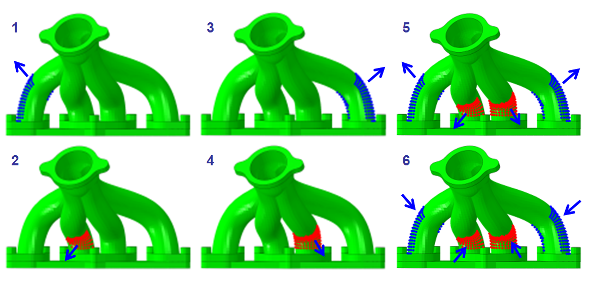
This file describes six morphing steps for four morphing areas Morph2, Morph3, Morph4, Morph1. The first four lines move the nodes of each MORPH_AREA by 1.0 each, starting with Morph2. Line 5 moves the nodes of all areas together by 1.0 outwards, and line 6 moves all nodes inwards.
 |