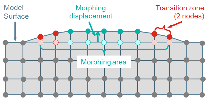
All nodes in one morphing area obtain the same morphing displacement
in one morphing step.
This may lead to unwanted sharp edges in your structure. Thus, transition
zones can be introduced for each morphing area. The transition zone is
formed by the nodes of the morphing area which are connected to the border
of the morph area by no more edges than specified with the TRANSITION_ZONE
command. These nodes will not be displaced by the same constant morphing
displacement applied to the rest of the morphing area but will be moved
back to an intermediate position to assure a smooth transition between,
e.g., two adjacent morphing areas or a morphing area and its surrounding
area.
Note:
- Mesh smoothing in general may not allow for smooth transitions between
single morphing areas as all morphing areas are part of one big design
area. This can only be ensured if each morphing area is surrounded by
some (at least 3-5) layers of nodes which do not belong to morphing areas.
If the model contains adjacent morphing areas, use the parameter TRANSITION_ZONE
of the MORPH_AREA command instead for smooth
results. The size of the transition zone should be in reasonable relation
to the size of the morphing area and the morphing displacement (e.g.
10% of the morphing area diameter or twice as large as the morphing
displacement).
- If a morph area with TRANSITION_ZONE>0 is situated
close to an edge of the geometry with an angle larger than 60° degree
no transition zone is chosen for this edge.
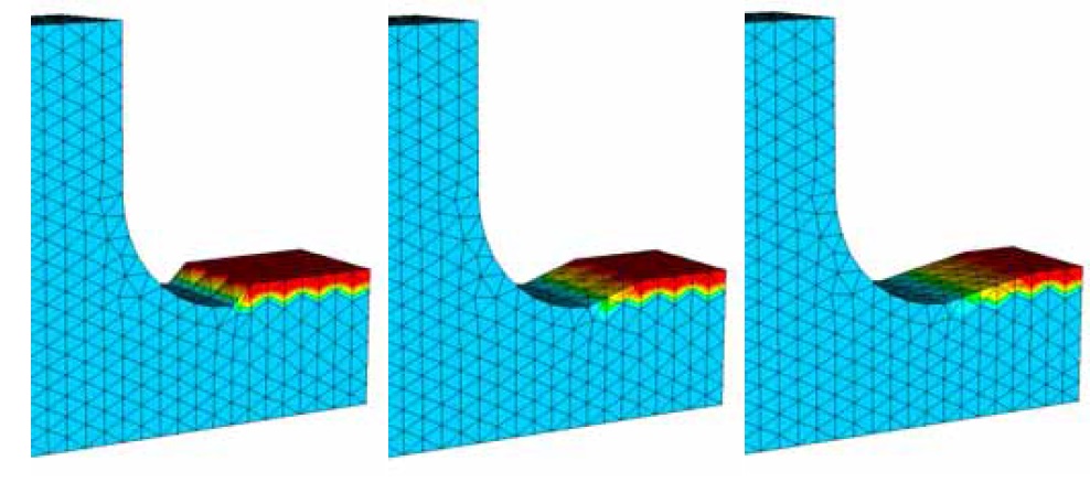
In the above figure the transition zone with 0, 2, and 4 layers is
demonstrated.

