Definition by Coordinates of Three Points | ||
| ||
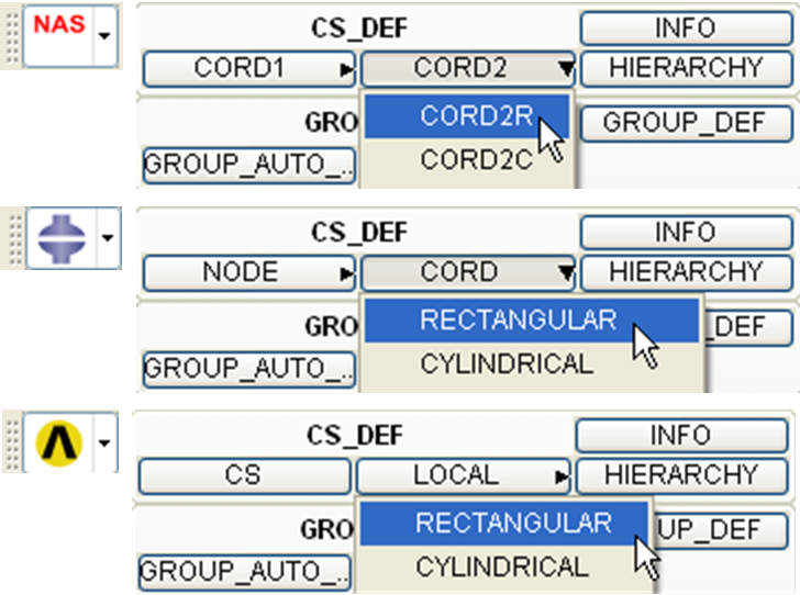
Instead of choosing three existing points, the coordinates of three arbitrary points, plus, optionally, one rotation angle can be used in order to define a coordinate system in Tosca ANSA® environment. In Tosca Structure.gui, this mode of coordinate system definition is not supported; see the next subsection. The following figure shows the definition of coordinate systems using coordinates in Tosca ANSA® environment:
 |
The commands creating the coordinate systems are found under the buttons CORD2 (Nastran), CORD (Abaqus) or LOCAL (ANSYS®), as well as in the context menu command New of the selection window for the coordinate systems:
Coordinate system type |
solver |
CS_DEF button label |
COORD database |
|---|---|---|---|
Cartesian |
Abaqus |
RECTANGULAR |
ORIENTATION_R |
OFFSET TO NODES |
ORIENTATION_OFFSET_TO_NODES |
||
Nastran |
CORD2R |
CORD_R |
|
ANSYS® |
RECTANGULAR |
LOCAL_R |
|
Cylindrical |
Abaqus |
CYLINDRICAL |
ORIENTATION_C |
Nastran |
CORD2C |
CORD_C |
|
ANSYS® |
CYLINDRICAL |
LOCAL_C |
|
Spherical |
Abaqus |
SPHERICAL |
ORIENTATION_S |
Nastran |
CORD2S |
CORD_S |
|
ANSYS® |
SPHERICAL |
LOCAL_S |
After a command is chosen, the user should select three points from the model. If a point close to an edge is clicked, the middle point of the edge is chosen; otherwise, if the point is close to a node, this node is chosen. Please take care not to select the edges in case you need the nodes. To do this, choose a point between the edges going from the node you wish to choose, sufficiently close to the node but not to any edge.
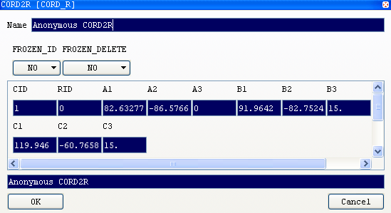
When all three nodes are chosen, the following dialog appears:
 |
This window contains the coordinates of the nodes that have just been chosen (A1..A3, B1..B3, C1..C3 fields). This coordinates may be modified; moreover, if it is needed to define the coordinate system using some points that not necessarily coincide with nodes or middle points of edges, the easiest way is to create a coordinate system using any three points and then to set the correct values in the fields of this dialog window.
The three points are used as follows:
- the first point (A1, A2, A3) is the origin;
- the direction from the origin to the second point (B1, B2, B3) is the direction of z-axis;
- x-axis lies in the plane defined by the three nodes, perpendicular to z-axis and closer to the direction from the origin to the third point (C1, C2, C3);
- y-axis is perpendicular to the other two, forming a positively oriented basis.
The field RID defines the reference coordinate system (by default, it is set to 0 indicating the global coordinate system). Pressing "?" key in this field opens the list of all defined coordinate systems. The values in A1..C3 fields are interpreted as the points with the corresponding coordinates with respect to the coordinate system that has ID equal to RID field, with RID = 0 corresponding to the global coordinate system.
Choosing Abaqus or ANSYS® as the solver allows (but not requires) the specification of one rotation angle using "rotation axis" field: choosing an axis (1 to 3, i.e., X to Z) in this field and then an angle in degrees in "rotation angle" field leads to the rotation of the new coordinate system around the specified axis (the "new" one, i.e., calculated basing on the chosen points).