How to create the optimization model | ||
| ||
The following describes the general procedure for the definition of an optimization task. These procedures are supported by the task manager in Tosca ANSA® environment (TAe) as well as the command tree in Tosca Structure.pre (GUI). The analysis model must be completely defined in advance.
Analysis Model
Question: Which file(s) contains the FE- model for the optimization?
Procedure: Link file(s) to optimization task.
In TAe: Select and choose your model file.
In GUI: Select and choose your model file.
![]()
Design Area
Question: Which surface area of the FE model should be selected regarding bead optimization?
Procedure: Assign node group with surface nodes to design area.
In TAe: and choose predefined group or select new group.
In GUI: Choose or define the node group with the surface nodes of the selected design area GROUP_DEF Command and define the design variables DV_BEAD.
Question: Are there nodes in the design area that are subject to certain restrictions? How can these restrictions be described?
Procedure: Define design variable constraints for node group. For sensitivity-based bead optimization nodes must be constrained in maximum positive and negative displacement.
In TAe: Select and choose predefined group or select new group for this restriction. If required, define link conditions using modules buttons.
In GUI: Choose or define node groups with common restrictions (GROUP_DEF). Define the restrictions using DVCON_BEAD.
Question: Are there certain symmetry conditions that should be fulfilled?
Procedure: Create a symmetry coupling condition.
In TAe:.
In GUI: Create a LINK_BEAD condition and reference it in a restriction command (DVCON_BEAD).
Note: LINK_BEAD is not supported by sensitivity-based bead optimization.
![]()
Objective Function
Question: Which terms describe the values to be optimized? Should these values be minimized or maximized or otherwise combined?
Procedure: Choose terms for optimization (design responses) and target.
In TAe: Select . Choose Edit for choice of target type (min, max, minmax).
In GUI: Define the design response (DRESP) and assign it to the objective function (OBJ_FUNC).
![]()
Constraint
Question: Which design response describes the constraint? Which value should the constraint have?
Procedure: Choose term for constraint and set target value or upper/lower boundary.
In TAe: Select
In GUI: Define the design response (DRESP) and assign it to the constraint (CONSTRAINT).
![]()
Optimization Task
Question: Are all of the command definitions listed above complete and ready for the optimization job?
Procedure: If necessary complete any additional required definitions and prepare the optimization job.
InTAe: Automatically prepared by task manager.
In GUI: Reference all definitions above in OPTIMIZE.
![]()
Stop Condition
Question: Should the optimization stop after a number of iterations (or certain other conditions)?
Procedure: Define a stop condition
In TAe: Select and change number of iterations.
In GUI: Select .
![]()
Check Run
Question: Would prior testing of the restriction definitions be useful?
Procedure: Apply test displacements
In TAe: Select or .
In GUI: Select .
![]()
Completion
Question: Has all the required data been specified?
Procedure: If yes, finish the definition of the optimization problem and save your definition.
In TAe: Select OUTPUT and change the jobname.
In GUI: Save as <jobname>.par.
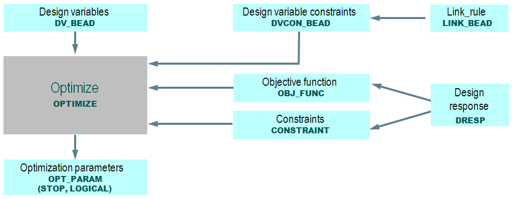
The definitions for the optimization job are assembled in a parameter file. The exact syntax of the commands can be looked up in the commands manual. The following figure shows an overview of a standard optimization task and the relation between the several commands. Only commands which are referenced in the OPTIMIZE command will be included in the optimization.
 |