Constraints | |||||||
|
| ||||||
Valid Design Response Types as Constraints
The following two tables describe which design response types are valid as constraints. These design responses can be constrained using equality constraint, lower equal constraint or greater equal constraint.
| Important: The equality constraint is only allowed for the controller-based topology optimization. The lower equal or greater equal constraints are allowed for the sensitivity-based approach as explained in Controller- Versus Sensitivity-Based Topology Optimization. The constraint values can be defined as absolute values or relative with respect to the corresponding values of the optimization start model. |
Moreover, for the sensitivity-based approach new combinations using VAR_OPER or GROUP_OPER for the DRESP can also be applied in the constraints:
Compliance terms for constraints |
Material volume terms for constraints |
Eigenfrequency terms for constraints |
|---|---|---|
|
Displacement terms for constraints |
Reaction force terms for constraints |
Internal force terms for constraints |
|---|---|---|
Von Mises stress terms for constraints |
Center of gravity terms for constraints |
Moment of inertia terms for constraints |
|---|---|---|
Note: Constraints defined using relative values always refer to the design response of the start model for the optimization.
Note: The element densities in the optimization start model may be modified compared to your original model (e.g. when no volume constraint is present they are set to 50% of the original density). Take this into account when defining, e.g., relative displacement or frequency constraints. This behavior can be controlled by the user with the parameter DENSITY_INITIAL in the OPT_PARAM command. For more information, see OPT_PARAM.
![]()
Multiple Material Constraints and Constitutive Laws
Multiple material constraints and constitutive laws are allowed in the design domain. I.e., different sub domains of the total design domain can be subject to different material volume constraints. Furthermore, different sub domains are allowed to have different constitutive material laws.
| Important: The DRESP WEIGHT_TOPO_FILL is not allowed when the design area contains different materials. |
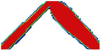
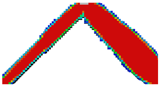
The following figure shows the design domain consisting of three different materials. Two volume constraints are applied in the design domain. The elements on the left side have the volume constraint of 20%, and the elements on the right side have the volume constraint of 40%.
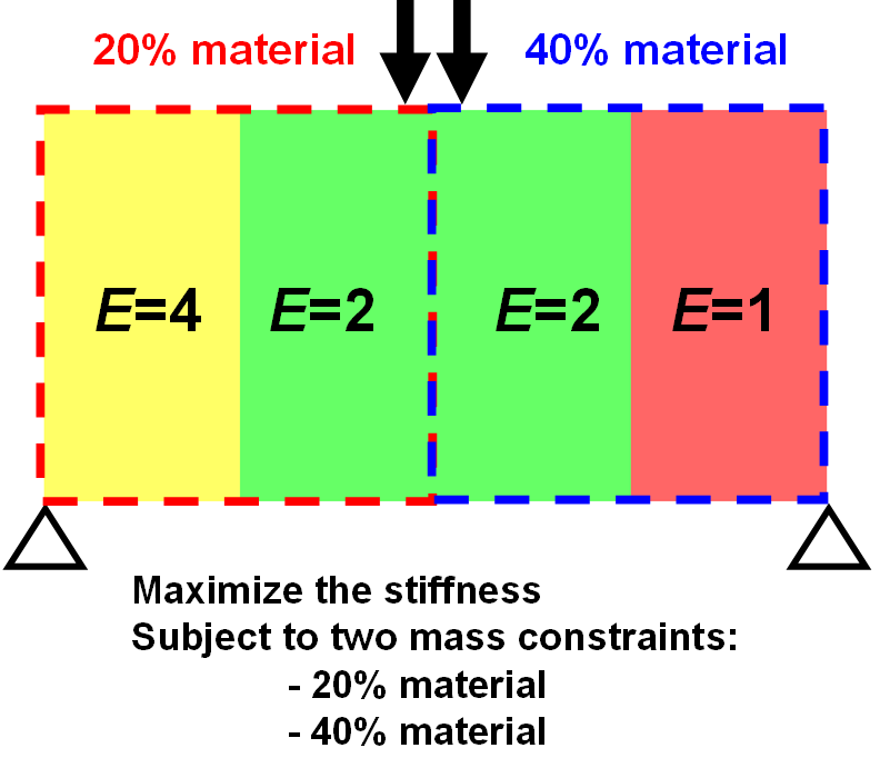 |
The design element group contains all elements:
DV_TOPO
 ID_NAME        = DESIGN_VARIABLES
 EL_GROUP       = ALL_ELEMENTS
END_
Then, using the groups ELEM_LEFT (left part of the model) and ELEM_RIGHT (right part of the model), two separate design responses are defined:
DRESP
 ID_NAME        = DRESP_VOL_TOPO_LEFT
 DEF_TYPE       = SYSTEM
 TYPE           = VOLUME
 EL_GROUP       = ELEM_LEFT
 GROUP_OPER     = SUM
END_
DRESP
 ID_NAME        = DRESP_VOL_TOPO_RIGHT
 DEF_TYPE       = SYSTEM
 TYPE           = VOLUME
 EL_GROUP       = ELEM_RIGHT
 GROUP_OPER     = SUM
END_
Afterwards, these design responses are applied in the relative volume constraints:
CONSTRAINT
 ID_NAME        = VOLUME_CONSTRAINT_LEFT
 DRESP          = DRESP_VOL_TOPO_LEFT
 MAGNITUDE      = REL
 LE_VALUE       = 0.2
END_
CONSTRAINT
 ID_NAME        = VOLUME_CONSTRAINT_RIGHT
 DRESP          = DRESP_VOL_TOPO_RIGHT
 MAGNITUDE      = REL
 LE_VALUE       = 0.4
END_
It is not allowed for the element groups with different volume constraints to have common elements. In other words, each element can be used in no more than one volume constraint. The compliance is minimized in the objective in order to maximize the stiffness:
DRESP
 ID_NAME        = DRESP_SUM_ENERGY
 DEF_TYPE       = SYSTEM
 TYPE           = STRAIN_ENERGY
 EL_GROUP       = ALL_ELEMENTS
 GROUP_OPER     = SUM
END_
OBJ_FUNC
 ID_NAME        = MAXIMIZE_STIFFNESS
 DRESP          = DRESP_SUM_ENERGY
 TARGET         = MIN
END_
Finally, the commands defined above are referenced in OPTIMIZE command:
OPTIMIZE
 ID_NAME        = TOPOLOGY_OPTIMIZATION
 DV             = DESIGN_VARIABLES
 OBJ_FUNC       = MAXIMIZE_STIFFNESS
 CONSTRAINT     = VOLUME_CONSTRAINT_LEFT
 CONSTRAINT     = VOLUME_CONSTRAINT_RIGHT
END_
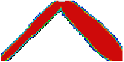
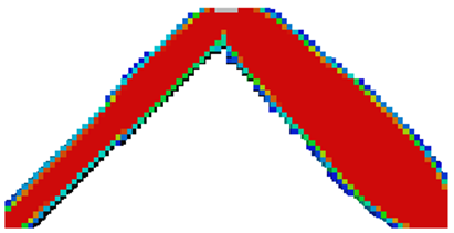
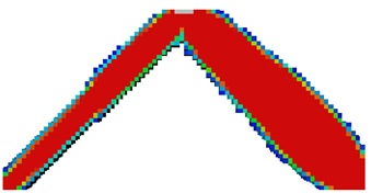
The following figures show the results of the optimization.
Abaqus |
ANSYS® |
||
 |
 |
||
Nastran |
MSC Marc® |
PERMAS® |
|
 |
 |
 |
|