PROJECTION CARTESIAN

Connection type PROJECTION CARTESIAN provides a connection between two nodes where the response in three local connection directions (that is, the axes of the local Cartesian coordinate system) is measured. Unlike the CARTESIAN connection, which uses an orthonormal coordinate system that follows node a, the PROJECTION CARTESIAN connection uses an orthonormal system that follows the systems at both nodes a and b.

The connector local directions used in the PROJECTION CARTESIAN connection are identical to those used in the PROJECTION FLEXION-TORSION connection. Connection type PROJECTION CARTESIAN is compatible with connection type PROJECTION FLEXION-TORSION and is appropriate for modeling the displacement response of bushing-like or spot-weld-like components.

Related Topics
Connector elements
Connector element library
In Other Guides
*CONNECTOR BEHAVIOR
*CONNECTOR SECTION

ProductsAbaqus/StandardAbaqus/ExplicitAbaqus/CAE

Description

Figure 1. Connection type PROJECTION CARTESIAN.

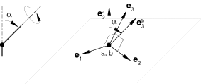
The PROJECTION CARTESIAN connection does not impose kinematic constraints. It defines three local directions {e1,e2,e3} as a function of the directions at both nodes a and b. These directions are the projection directions defined by the PROJECTION FLEXION-TORSION connection. The PROJECTION CARTESIAN connection measures the change in position of node b relative to node a along the (projection) coordinate directions {e1,e2,e3}.

The position of node b relative to node a is

x=e1(xb-xa);    y=e2(xb-xa);    and    z=e3(xb-xa).

The available components of relative motion are

u1=x-x0;    u2=y-y0;    and    u3=z-z0,

where x0, y0, and z0 are the initial coordinates of node b relative to node a along the initial {e1,e2,e3} directions. The connector constitutive displacements are

u1mat=x-l1ref;    u2mat=y-l2ref;    and    u3mat=z-l3ref.

The local directions in a PROJECTION CARTESIAN connection are “centered” between the systems at the two connector nodes. PROJECTION CARTESIAN connections are appropriate where isotropic or anisotropic material response is modeled and the local material directions evolve as a function of the rotations at both ends of the connection. The kinetic force is

fprojCart=f1e1+f2e2+f3e3.

In two-dimensional analysis z=0, u3=0, u3mat=0, and f3=0.

Summary

PROJECTION CARTESIAN
Basic, assembled, or complex: Basic
Kinematic constraints: None
Constraint force output: None
Available components: u1,u2,u3
Kinetic force output: f1,f2,f3
Orientation at a: Optional
Orientation at b: Optional
Connector stops: l1minxl1max,
  l2minyl2max,
  l3minzl3max
Constitutive reference lengths: l1ref,l2ref,l3ref
Predefined friction parameters: None
Contact force for predefined friction: None