EULER | |||||||||
|
| ||||||||
ProductsAbaqus/StandardAbaqus/ExplicitAbaqus/CAE
Description
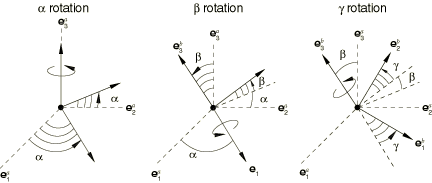
The EULER connection does not impose kinematic constraints. An EULER connection is a finite rotation connection where the local directions at node b are parameterized in terms of Euler angles relative to the local directions at node a. Local directions are positioned relative to by three successive finite rotations , , and as follows:
Rotate by radians about axis ;
Rotate by radians about the intermediate 1-axis, ;
Rotate by radians about axis .
The Euler angles are determined by the local directions as
Here i, j, and k are integers that account for rotations with magnitudes greater than . Initially, the intermediate rotation angle is chosen in the interval .
If the intermediate rotation is an even multiple of , , where , the other two Euler angles become non-unique. In this case
Similarly, if the intermediate rotation is an odd multiple of , , where 0, , the other two Euler angles become nonunique as well. In this case
In both of these cases a singularity results in the rotation parameterization when the and axes align. The EULER connection should be used in such a way that these axes do not align throughout the computation. For a singularity-free condition Abaqus will choose and such that a smooth parameterization results for the above values of the intermediate angle .
The available components of relative motion in the EULER connection are the changes in the Euler angles that position the local directions at node b relative to the local directions at node a. Therefore,
where , , and are the initial Euler angles. The connector constitutive rotations are
The kinetic moment in a EULER connection is determined from the three component relationships:
![]()
Summary
| ||||||||||||||||||||||||||||