Context:
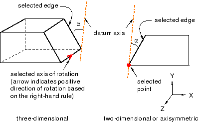
The figures below show examples of creating a datum axis by rotating an
existing edge through a specified angle.

From the main menu bar, select
.
The Create Datum dialog box appears. The dialog
box outlines the types of datum geometry you can create.
Abaqus/CAE displays prompts in the prompt area to guide you through the procedure.
From the list of types at the top of the dialog box, choose
Axis.
The Method list indicates the methods you can
use to create a datum axis.
From the Method list, select Rotate
from line.
If desired, select Make Independent from the
prompt area to create the datum as an independent feature.
From the part or assembly in the current viewport, select an edge or a
datum axis to rotate.
The technique for specifying the rotation depends on the modeling
space of the part or assembly:
- For a two-dimensional or
axisymmetric part or assembly:
-
-
Select a vertex or datum point at the center of rotation. You can
also use the text box that appears in the prompt area to enter the precise
coordinates of the center of rotation.
-
In the text box in the prompt area, enter the angle of rotation. A
positive angle indicates a counterclockwise rotation about the
Z–axis.
The datum axis appears.
- For a
three-dimensional part or assembly:
-
-
Select an edge or a datum axis to represent the axis of rotation.
Abaqus/CAE
displays an arrow along the selected edge indicating the positive direction of
rotation using the right-hand rule.
-
In the text box that appears in the prompt area, type the angle of
rotation.
The datum axis appears.
You can modify the angle of rotation by selecting
from the main menu bar and selecting the datum axis. If you change the sign of
the angle,
Abaqus/CAE
reverses the direction of rotation.
