Creating a datum axis along the axis of a cylinder

You can position a datum axis by selecting a cylindrical or conical face on the model. Abaqus/CAE creates a datum axis that lies along the axis of the face.

Related Topics
Methods for creating a datum axis
Datum creation techniques
Controlling datum display

Context:

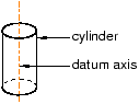
The figure below shows an example of creating a datum axis along the axis of a cylinder.


  1. From the main menu bar, select ToolsDatum.

    The Create Datum dialog box appears. The dialog box outlines the types of datum geometry you can create.

    Abaqus/CAE displays prompts in the prompt area to guide you through the procedure.

    Tip: You can also create a datum axis using the tool, located in the module toolbox. For a diagram of the datum tools in the toolbox, see Using the Datum toolset.

  2. From the list of types at the top of the dialog box, choose Axis.

    The Method list indicates the methods you can use to create a datum axis.

  3. From the Method list, select Axis of cylinder.

  4. If desired, select Make Independent from the prompt area to create the datum as an independent feature.

  5. From the part or assembly in the current viewport, select a a cylindrical or conical face.

    The datum axis appears. You cannot modify a datum axis created with this method; you must delete the old axis and create a new one.