Defining the Input Parameters | ||
| ||
Click the Input tab on the Simcode Component Editor.
The contents of the tab appear.
Click the large Click here to open a new Data Source button in the center of the tab.
The Quick Data Source Configuration dialog box appears.
Tip: If you want to use the Exchanger Wizard, click Advanced (see Configure the Input Using the Exchanger Wizard) in the Isight Component Guide. Click Browse.
The Open dialog box appears.
Select the AeroIn.txt file, and click Open.
Note: If you are using Linux, select AeroIn from the subdirectory that matches your operating system.
The full path of the file is added to the Template File text box.
Verify that the General Text option is highlighted in the Format area, and click OK.
Isight can perform data exchange (or parsing) on four different types of files: General Text, Name/Value, Table, and Vector. For this example, you will use the General Text file type.
Click OK.
You are returned to the component editor, and the input file information is displayed.
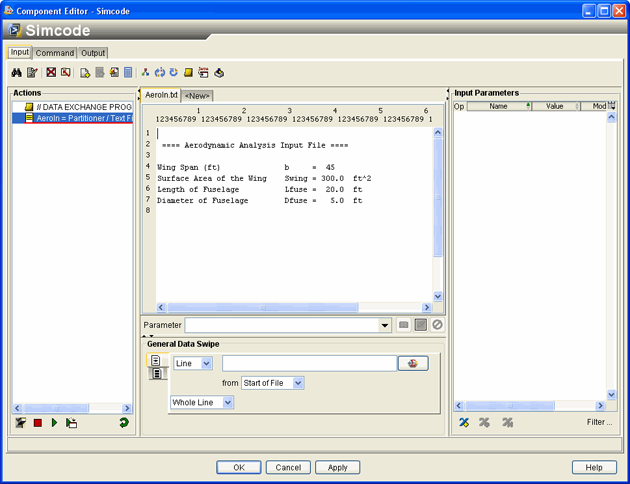
The left side of the editor shows the current list of actions for the file. The center of the editor shows the contents of the template input file used by the simulation code. The right side displays the input parameters with properties such as Mode, Type, etc. Because you have not defined any parameters, this area is blank.
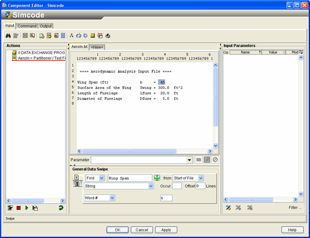
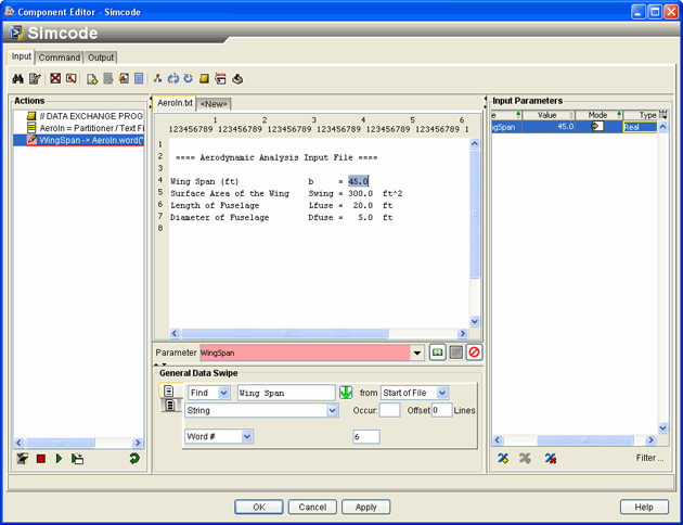
To convert the wingspan to a parameter, click the value of the wingspan (45) in the editor.
The number is highlighted.
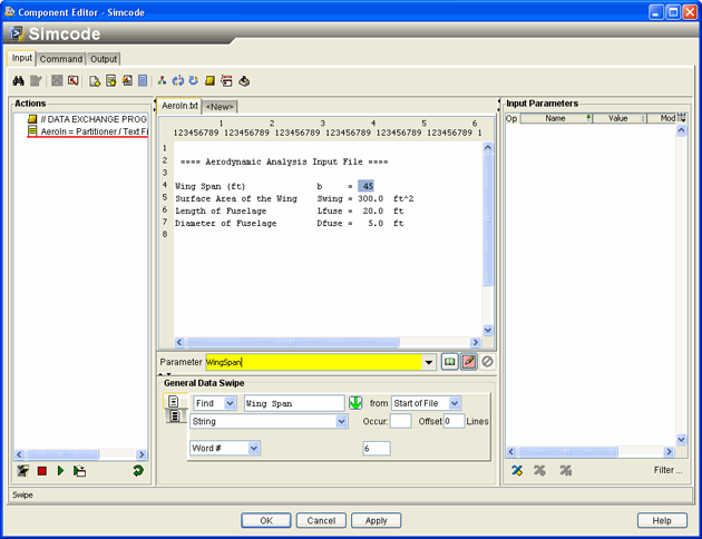
Type WingSpan in the Parameter text box in the center of the editor.
Once you begin to enter text, the text box is highlighted in yellow to indicate that the parameter does not exist but will be created.
Click the Write
 button adjacent to the Parameter
text box.
This action tells Isight to write a parameter called WingSpan into the input file at the location where the value 45 now resides. For the purpose of file parsing in the Simcode component, Isight typically writes parameters into the input file so that their values may change from run to run. Conversely, Isight reads values from output files after they are run through the Simcode.
The editor is updated with the new action added to the Actions list and the new parameter added to the Input Parameters list.
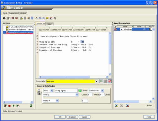
The parameter WingSpan was assumed to be an integer, because the number in the input file is written without decimals. However, for this example the value is a real number. Click the cell that contains the word Integer in the Input Parameters area of the right side of the editor. You may need to scroll over to see this cell under the Type column.
A list of variable types appears.
Select Real.
The Type setting for the WingSpan parameter is updated.
Now you need to define the remaining input parameters using the same procedure.
Click the value 300.0 in the center of the editor until the number is highlighted.
Type WingArea in the Parameter text box, and click the Write
 button.
The Actions list is updated, and this parameter is added to the Input Parameters list on the right side of the editor. Because the value in the file is in real format, the parameter WingArea is assumed to be a real value.
Click the value 20.0 in the center of the editor until the number is highlighted.
Type FuseLength in the Parameter text box, and click the Write
 button.
The Actions list is updated, and the parameter is added to the Input Parameters list.
Click the value 5.0 in the center of the editor until the number is highlighted.
Type FuseDia in the Parameter text box, and click the Write
 button.
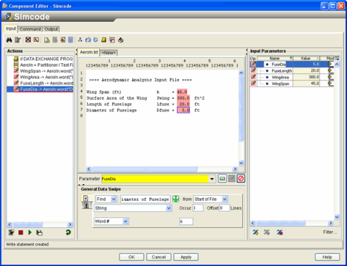
The Actions list is updated, and the parameter is added to the Input Parameters list. When finished, your editor will appear as shown below.
Click Apply to save your changes to the component.