About Models | ||
| ||
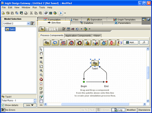
You can visually display models in the Design Gateway on the Sim-flow tab. The following shows an example of an empty model with a Task component as the root (top-level) component in the Design Gateway:

A model consists of a simulation process flow, data (e.g., parameters, files), configuration settings (e.g., component configuration, model properties), and graphs and tables. A simulation process flow is the collection of tasks, calculations, and computations arranged in some meaningful manner. A model can contain only one simulation process flow that can be hierarchical. Each step in a simulation process flow is called a component. A component may be based on native Isight tools, or it may invoke third-party applications such as CAD/CAE software, Excel worksheets, or custom in-house programs. The components communicate with each other by passing data through parameters.
For information about the typical model development process and working with models, see About the Model Development Sequence.
An Isight model:
-
provides a representation of your design process,
-
defines a meaningful relationship between components (the simulation process flow),
-
specifies data sources and data dependencies, and
-
allows you to define standard best practices.
These characteristics are stored as a zipped model file (*.zmf). This file contains references to components and configuration information (e.g., properties, parameters) for specific use by each component. In addition, relationships between the components are stored in the file.